


NX50 Troubleshooting Manual
Responding to alarms
Page 1-28
Issue 6.0 2019-04-01
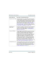
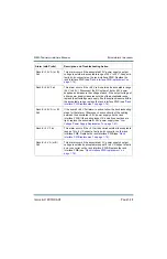
Module #: High DC
Current
This alarm indicates that the RF power module's DC Current
meter has exceeded 22 A, or the RF power module's peak DC
current has exceeded the threshold applied to the
microcontroller's comparator. This alarm will immediately disable
the RF power module, and latch it off. If this alarm occurred in
conjunction with an Overmodulation alarm, follow the
troubleshooting action for that alarm. Otherwise, try resetting the
alarms using the AUI. If the alarm persists, replace the RF power
module. If the alarm clears, troubleshoot the suspect RF power
module for RF FET failures (see
).
If the alarm persists, suspect that the
associated RF relay is not opening, or the associated gas
discharge tube has activated.
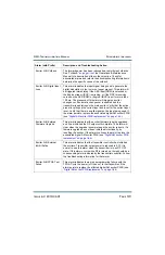
Module #: High PA
Voltage
This alarm occurs because of one of two conditions: (1) the PA
voltage is at least 10% above the product of the B+ level and the
PDM duty cycle; or (2) the PA voltage has exceeded 95% of the
B+ value for more than 50 ms. The alarm is latching and will
cause the associated RF power module to disable itself. This
alarm generally indicates that a modulator FET has failed. See
“Troubleshooting RF power modules” on page 1-56
to determine
whether to replace the affected RF power module or to repair
damaged parts.
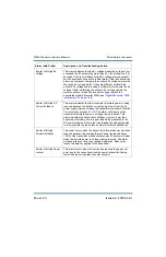
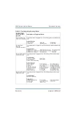
Module #: High RF Drive
This alarm indicates the RF drive duty cycle as measured by the
RF power module is above 65%. The affected RF power module
is immediately disabled. Try swapping the affected RF power
module with an operational RF power module in another position.
If the fault follows the RF power module, replace the RF power
module (see
“Removing an RF power module” on page 1-51
). If
the fault remains with that position,
and is also present on an
adjacent power module, try replacing the associated RF Drive
cable. If the alarm persists, replace the RF Drive Distribution PWB
(see
“RF drive distribution PWB replacement” on page 1-74
.
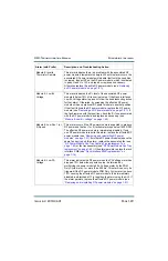
Module #: High
Temperature
This alarm indicates the power module's measured heatsink
temperature has exceeded 90 degrees Celsius. The affected RF
power module is immediately disabled. If this alarm occurs with
another alarm, troubleshoot that alarm first. Otherwise, see
“Troubleshooting RF power modules” on page 1-56
to determine
whether to replace the affected RF power module or to repair
damaged parts.
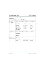
Alarm (with Prefix)
Description and Troubleshooting Action
Summary of Contents for NX50
Page 2: ......
Page 4: ......
Page 8: ...NX50 Troubleshooting Manual Page viii Issue 6 0 2019 04 01...
Page 10: ...NX50 Troubleshooting Manual Page x Issue 6 0 2019 04 01...
Page 108: ...NX50 Troubleshooting Manual Responding to alarms Page 1 98 Issue 6 0 2019 04 01...
Page 153: ...NX50 Troubleshooting Manual Reading Electrical Schematics Page 4 6 Issue 6 0 2019 04 01...
Page 184: ...Issue 6 0 2019 04 01 MD 4 Figure MD 4 NAPI95A 01 Power Module Interface PWB...
Page 188: ...Issue 6 0 2019 04 01 MD 8 Figure MD 8 NAPI106 Remote Interface PWB...
Page 192: ...Issue 6 0 2019 04 01 MD 12 Figure MD 12 NAPI98 RF Drive Distribution PWB...
Page 198: ...Issue 6 0 2019 04 01 MD 18 Figure MD 18 Fan Tray Assembly 207 8133 B1 B2 J1 AIR FLOW AIR FLOW...
Page 201: ...Issue 6 0 2019 04 01 MD 21 Figure MD 21 NAFP106B 01 Directional Coupler A1 DETAIL...
Page 204: ......


