


NX50 Troubleshooting Manual
Responding to alarms
Page 1-52
Issue 6.0 2019-04-01
6. Grasp the handle on the front of the RF power module and carefully pull the RF
power module out of the transmitter.
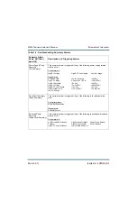
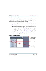
Figure 1.5: Disabling/Enabling an RF Power Module
NOTE:
To maintain proper airflow in the transmitter, install the dummy module
assembly (Nautel part # 207-1038, located in the NX50 ancillary kit) if a
replacement RF power module is not readily available after removing the
defective module.
Green indicates enabled. Click to disable (will turn red);
click again to re-enable (will turn green)
Summary of Contents for NX50
Page 2: ......
Page 4: ......
Page 8: ...NX50 Troubleshooting Manual Page viii Issue 6 0 2019 04 01...
Page 10: ...NX50 Troubleshooting Manual Page x Issue 6 0 2019 04 01...
Page 108: ...NX50 Troubleshooting Manual Responding to alarms Page 1 98 Issue 6 0 2019 04 01...
Page 153: ...NX50 Troubleshooting Manual Reading Electrical Schematics Page 4 6 Issue 6 0 2019 04 01...
Page 184: ...Issue 6 0 2019 04 01 MD 4 Figure MD 4 NAPI95A 01 Power Module Interface PWB...
Page 188: ...Issue 6 0 2019 04 01 MD 8 Figure MD 8 NAPI106 Remote Interface PWB...
Page 192: ...Issue 6 0 2019 04 01 MD 12 Figure MD 12 NAPI98 RF Drive Distribution PWB...
Page 198: ...Issue 6 0 2019 04 01 MD 18 Figure MD 18 Fan Tray Assembly 207 8133 B1 B2 J1 AIR FLOW AIR FLOW...
Page 201: ...Issue 6 0 2019 04 01 MD 21 Figure MD 21 NAFP106B 01 Directional Coupler A1 DETAIL...
Page 204: ......


