


NX50 Troubleshooting Manual
Responding to alarms
Issue 6.0 2019-04-01
Page 1-55
Optimizing RF power module Performance
When swapping damaged RF power modules with new RF power modules, it is possible that
spurs of the fundamental PDM frequency (fc ± 155 kHz) may appear at the output of the
transmitter. If these spurs violate the emissions limits of the region of installation, the problem
may be corrected by initiating the PDM minimization routine, as follows:
1. Turn off (RF Off) and connect the RF output to a suitably rated 50-ohm test load.
2. Using the AUI, set the following items as instructed:
• Overall Mode = Analog AM
• Output Power = rated power
• AM Source = Unused
3. Set the transmitter to its RF On state.
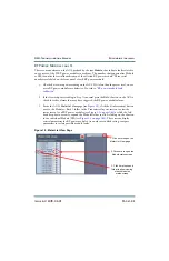
4. Using the AUI, navigate to the PDM minimization routine through Menu -> Factory
Settings -> PDM Settings page, and click on the Start button next to Minimization
Routine.
The PDM minimization routine requires approximately 30 minutes to complete.
CAUTION:
Running the PDM minimization routine will disable the exciter’s SWR protection.
For this reason, you should only run this routine when the transmitter is
connected to a suitably rated 50 ohm test load.
Summary of Contents for NX50
Page 2: ......
Page 4: ......
Page 8: ...NX50 Troubleshooting Manual Page viii Issue 6 0 2019 04 01...
Page 10: ...NX50 Troubleshooting Manual Page x Issue 6 0 2019 04 01...
Page 108: ...NX50 Troubleshooting Manual Responding to alarms Page 1 98 Issue 6 0 2019 04 01...
Page 153: ...NX50 Troubleshooting Manual Reading Electrical Schematics Page 4 6 Issue 6 0 2019 04 01...
Page 184: ...Issue 6 0 2019 04 01 MD 4 Figure MD 4 NAPI95A 01 Power Module Interface PWB...
Page 188: ...Issue 6 0 2019 04 01 MD 8 Figure MD 8 NAPI106 Remote Interface PWB...
Page 192: ...Issue 6 0 2019 04 01 MD 12 Figure MD 12 NAPI98 RF Drive Distribution PWB...
Page 198: ...Issue 6 0 2019 04 01 MD 18 Figure MD 18 Fan Tray Assembly 207 8133 B1 B2 J1 AIR FLOW AIR FLOW...
Page 201: ...Issue 6 0 2019 04 01 MD 21 Figure MD 21 NAFP106B 01 Directional Coupler A1 DETAIL...
Page 204: ......


