


NX50 Troubleshooting Manual
Responding to alarms
Issue 6.0 2019-04-01
Page 1-87
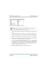
6. The new monitor may require calibration after installation. If necessary, connect a
USB mouse to a USB port on the Single Board Computer and do the following:
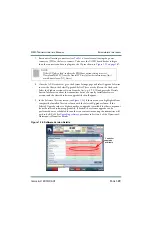
• On the local AUI, go to
Menu
>
System Settings
>
Screen Configuration
.
• Press the Touchscreen Calibration button. This will initiate a calibration screen
where you will be prompted to sequentially touch three targets from a position of
normal use. Touch each target. After the third target, the calibration is complete
and the screen display returns to the
Screen Configuration
page.
The replacement procedure is complete.
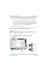
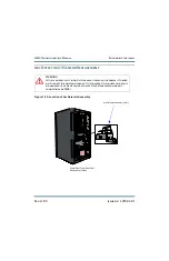
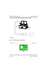
Single Board Computer (SBC) Replacement
Figure 1.23: Single-Board Computer A1 (on the back of the front door)
NOTE:
The replacement SBC assembly is static sensitive and can be damaged by
electrostatic discharge. Observe the static precautions described in
at all times.
COM
COM1
(W67P2)
VGA1
CPU 12V1
(P30)
A1TB1-RESET
(P33)
NX v4.X
LAN1
USB
FLASH
CARD
W66P2
RED WIRE
BOTTOM RIGHT
RED WIRE TOP LEFT
Summary of Contents for NX50
Page 2: ......
Page 4: ......
Page 8: ...NX50 Troubleshooting Manual Page viii Issue 6 0 2019 04 01...
Page 10: ...NX50 Troubleshooting Manual Page x Issue 6 0 2019 04 01...
Page 108: ...NX50 Troubleshooting Manual Responding to alarms Page 1 98 Issue 6 0 2019 04 01...
Page 153: ...NX50 Troubleshooting Manual Reading Electrical Schematics Page 4 6 Issue 6 0 2019 04 01...
Page 184: ...Issue 6 0 2019 04 01 MD 4 Figure MD 4 NAPI95A 01 Power Module Interface PWB...
Page 188: ...Issue 6 0 2019 04 01 MD 8 Figure MD 8 NAPI106 Remote Interface PWB...
Page 192: ...Issue 6 0 2019 04 01 MD 12 Figure MD 12 NAPI98 RF Drive Distribution PWB...
Page 198: ...Issue 6 0 2019 04 01 MD 18 Figure MD 18 Fan Tray Assembly 207 8133 B1 B2 J1 AIR FLOW AIR FLOW...
Page 201: ...Issue 6 0 2019 04 01 MD 21 Figure MD 21 NAFP106B 01 Directional Coupler A1 DETAIL...
Page 204: ......


