


NX50 Troubleshooting Manual
Responding to alarms
Issue 6.0 2019-04-01
Page 1-45
RF Power Module faults
There are many alarms on the AUI, prefixed by the text
Module
, that indicate faults related to
one or more of the 20 RF power modules in a cabinet. The number that appears after Module
or PM, identifies the serial identification of the affected RF power module. These serial
numbers are labeled on the front panel of each RF power module.
1. Check the forward power reading on the AUI. If it is less than the preset level, one or
more RF power modules are defective. Proceed to
2. If the forward power reading in
Status
button on the AUI to
check for other alarms that may have triggered the RF power module alarm.
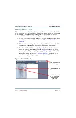
3. From the AUI’s
Meter List View
page (see
), click the
i
(information) button
next to the Modules - Rack
1
folder in the Transmitter Layout section to view the
status screen for all RF power modules (see
hand drop down arrow to expand the Modules folder to allow clicking on the
i
button
for an individual Module (PM) (see
). These screens display
critical parameters for RF power modules. As an aid in troubleshooting, compare
parameters to isolate possible module faults.
Figure 1.2: Meter List View Page
1. Click here to open the
Meter List View page
2. Click here to open the
Module status screen
3. Click here to expand
folder to allow viewing
of each Module’s
status screen
Summary of Contents for NX50
Page 2: ......
Page 4: ......
Page 8: ...NX50 Troubleshooting Manual Page viii Issue 6 0 2019 04 01...
Page 10: ...NX50 Troubleshooting Manual Page x Issue 6 0 2019 04 01...
Page 108: ...NX50 Troubleshooting Manual Responding to alarms Page 1 98 Issue 6 0 2019 04 01...
Page 153: ...NX50 Troubleshooting Manual Reading Electrical Schematics Page 4 6 Issue 6 0 2019 04 01...
Page 184: ...Issue 6 0 2019 04 01 MD 4 Figure MD 4 NAPI95A 01 Power Module Interface PWB...
Page 188: ...Issue 6 0 2019 04 01 MD 8 Figure MD 8 NAPI106 Remote Interface PWB...
Page 192: ...Issue 6 0 2019 04 01 MD 12 Figure MD 12 NAPI98 RF Drive Distribution PWB...
Page 198: ...Issue 6 0 2019 04 01 MD 18 Figure MD 18 Fan Tray Assembly 207 8133 B1 B2 J1 AIR FLOW AIR FLOW...
Page 201: ...Issue 6 0 2019 04 01 MD 21 Figure MD 21 NAFP106B 01 Directional Coupler A1 DETAIL...
Page 204: ......