


NX50 Troubleshooting Manual
Responding to alarms
Issue 6.0 2019-04-01
Page 1-17
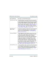
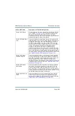
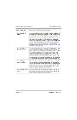
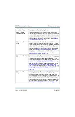
Controller: Rack 1 Not
Responding
This alarm indicates that the controller is no longer receiving serial
communication from Rack 1. No action is taken. Check the wiring
and connections between the control/interface PWB and the rack
interface PWB and verify there is no damage. If the wiring is OK,
replace the control/interface PWB (see
). If the alarm persists, replace the
affected cabinet’s rack interface PWB (see
).
Controller: Unknown
Reset Cause
This alarm is only visible in the transmitter logs, and indicates the
controller was reset, but it was unable to determine the cause of
the reset.
If
the controller is rebooting unexpectedly, check for the
presence of other alarms at the time of this alarm and follow the
troubleshooting action for the associated alarm(s). Otherwise,
replace the control/interface PWB (see
).
Exciter A/B: AES1 (or 2)
Unlocked
This alarm indicates there is no AES data detected on the
applicable AES (1 or 2) input and that same input is selected as
the active input in either Analog or Digital settings for the active
preset. Verify there is valid AES data being applied to the
corresponding input on the control/interface PWB. If there is data
being applied to the correct input and the alarm persists, replace
the digital AM exciter PWB (see
) or the control/interface PWB (see
“Control/interface PWB replacement” on page 1-64
Exciter A/B: AM Input
Loss
This alarm occurs if the input signal being used to generate the
analog AM modulation is low or not present. This alarm will be
triggered immediately if the AES input is unlocked, or after 2
minutes if the incoming modulation level is below 10%. The
presence of this alarm will trigger an exciter changeover if
automatic changeover is enabled and the transmitter is operating
on the main exciter. Verify that the active preset is calling up the
correct audio input and is set for the correct input level. Verify that
there is a valid audio signal on the audio input being used. If the
alarm persists, replace the associated digital AM exciter PWB
(see
“Digital AM exciter PWB replacement” on page 1-66
Alarm (with Prefix)
Description and Troubleshooting Action
Summary of Contents for NX50
Page 2: ......
Page 4: ......
Page 8: ...NX50 Troubleshooting Manual Page viii Issue 6 0 2019 04 01...
Page 10: ...NX50 Troubleshooting Manual Page x Issue 6 0 2019 04 01...
Page 108: ...NX50 Troubleshooting Manual Responding to alarms Page 1 98 Issue 6 0 2019 04 01...
Page 153: ...NX50 Troubleshooting Manual Reading Electrical Schematics Page 4 6 Issue 6 0 2019 04 01...
Page 184: ...Issue 6 0 2019 04 01 MD 4 Figure MD 4 NAPI95A 01 Power Module Interface PWB...
Page 188: ...Issue 6 0 2019 04 01 MD 8 Figure MD 8 NAPI106 Remote Interface PWB...
Page 192: ...Issue 6 0 2019 04 01 MD 12 Figure MD 12 NAPI98 RF Drive Distribution PWB...
Page 198: ...Issue 6 0 2019 04 01 MD 18 Figure MD 18 Fan Tray Assembly 207 8133 B1 B2 J1 AIR FLOW AIR FLOW...
Page 201: ...Issue 6 0 2019 04 01 MD 21 Figure MD 21 NAFP106B 01 Directional Coupler A1 DETAIL...
Page 204: ......


