


NX50 Troubleshooting Manual
Responding to alarms
Issue 6.0 2019-04-01
Page 1-77
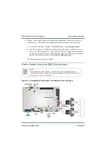
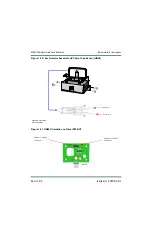
6. Remove the Rack Interface PWB from the transmitter. You may notice some
resistance as the PWB disengages from the three (3) D-sub connectors on the front edge
of the board which mate to the power module interface PWBs.
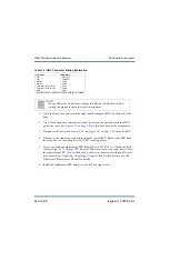
7. Obtain a replacement Rack Interface PWB (Nautel Part # NAPI152C) and set DIP
switch S1 as follows:
8. Reverse
to reinstall the PWB. Ensure all connections are tight
taking special precaution to verify the three (3) D-sub connectors mentioned in Step 6
are fully mated. It may be helpful to verify prior to re-installing the RF Drive
Distribution PWB. For connector mating assistance, refer to the connector mating
tables in
Section 3, “Wiring/connector lists” on page 3-1
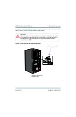
9. Disengage all RF power modules in the transmitter before turning on the ac power (see
“Removing and reinstalling RF power modules” on page 1-51
).
10. Close and lock the rear door. Enable (switch on) the ac power for the transmitter.
11. One at a time, insert an RF power module and wait for the LED sequence on the front
panel change to solid red. Reconnect the RF power module’s PDM cable; the LED
sequence should change to flashing amber.
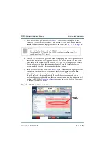
12. Upgrade the subsystem software using the AUI’s
Upgrade Software
page under the
System Settings
menu by running an upgrade using the existing .tgz file already
installed on the transmitter. See the
NX50 Operations and Maintenance Manual
for
detailed instructions.
13. Set the transmitter to its RF ON state. Ensure any previously present alarms have
cleared.
S1 Position
A6 Setting
8
CLOSED
7
CLOSED
6
OPEN
5
CLOSED
4
CLOSED
3
CLOSED
2
OPEN
1
OPEN
Summary of Contents for NX50
Page 2: ......
Page 4: ......
Page 8: ...NX50 Troubleshooting Manual Page viii Issue 6 0 2019 04 01...
Page 10: ...NX50 Troubleshooting Manual Page x Issue 6 0 2019 04 01...
Page 108: ...NX50 Troubleshooting Manual Responding to alarms Page 1 98 Issue 6 0 2019 04 01...
Page 153: ...NX50 Troubleshooting Manual Reading Electrical Schematics Page 4 6 Issue 6 0 2019 04 01...
Page 184: ...Issue 6 0 2019 04 01 MD 4 Figure MD 4 NAPI95A 01 Power Module Interface PWB...
Page 188: ...Issue 6 0 2019 04 01 MD 8 Figure MD 8 NAPI106 Remote Interface PWB...
Page 192: ...Issue 6 0 2019 04 01 MD 12 Figure MD 12 NAPI98 RF Drive Distribution PWB...
Page 198: ...Issue 6 0 2019 04 01 MD 18 Figure MD 18 Fan Tray Assembly 207 8133 B1 B2 J1 AIR FLOW AIR FLOW...
Page 201: ...Issue 6 0 2019 04 01 MD 21 Figure MD 21 NAFP106B 01 Directional Coupler A1 DETAIL...
Page 204: ......


