


NX50 Troubleshooting Manual
Responding to alarms
Issue 6.0 2019-04-01
Page 1-53
Installing an RF power module
1. If possible, turn off the transmitter before installing an RF power module. Grasp the
handle on the front of the RF power module and insert it into the transmitter.
2. Carefully push the RF power module into place so that its card-edge connector mates
with the transmitter. Verify the RF power module is fully inserted by ensuring the
faceplate of the RF power module is touching the transmitter chassis that it mates
with.
3. Install both mounting screws in the RF power module’s front panel.
4. Connect the PDM cable (RJ45 connector) to the front of the RF power module.
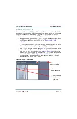
5. If the RF power module was disabled through the AUI, enable it as follows:
• From the Meters page, click on the Modules - Rack information (i) button. The
Power Module status screen (see
) should appear. Click on
the associated RF power module’s Front Panel Inhibit icon. The icon colour
should change from red to green, indicating the RF power module is enabled.
You should hear a relay in the back of the transmitter pick up (energize).
6. If the RF power module being installed is a replacement, upgrade the subsystem
software using the AUI’s
Upgrade Software
page under the
System Settings
menu by
running an upgrade using the existing .tgz file already installed on the transmitter. See
the
NX50 Operations and Maintenance Manual
for detailed instructions
Summary of Contents for NX50
Page 2: ......
Page 4: ......
Page 8: ...NX50 Troubleshooting Manual Page viii Issue 6 0 2019 04 01...
Page 10: ...NX50 Troubleshooting Manual Page x Issue 6 0 2019 04 01...
Page 108: ...NX50 Troubleshooting Manual Responding to alarms Page 1 98 Issue 6 0 2019 04 01...
Page 153: ...NX50 Troubleshooting Manual Reading Electrical Schematics Page 4 6 Issue 6 0 2019 04 01...
Page 184: ...Issue 6 0 2019 04 01 MD 4 Figure MD 4 NAPI95A 01 Power Module Interface PWB...
Page 188: ...Issue 6 0 2019 04 01 MD 8 Figure MD 8 NAPI106 Remote Interface PWB...
Page 192: ...Issue 6 0 2019 04 01 MD 12 Figure MD 12 NAPI98 RF Drive Distribution PWB...
Page 198: ...Issue 6 0 2019 04 01 MD 18 Figure MD 18 Fan Tray Assembly 207 8133 B1 B2 J1 AIR FLOW AIR FLOW...
Page 201: ...Issue 6 0 2019 04 01 MD 21 Figure MD 21 NAFP106B 01 Directional Coupler A1 DETAIL...
Page 204: ......


