


NX50 Troubleshooting Manual
Responding to alarms
Issue 6.0 2019-04-01
Page 1-79
2. If you are troubleshooting a rectifier fan alarm see "
,
).
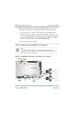
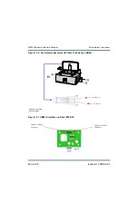
3. Disconnect all wiring attached to the SCR rectifier assembly’s A (LINE 1), B (LINE 2),
C (LINE 3), DC (+), DC (-), TB1, TB2 and TB3 terminals, taking note of the wiring
labels.
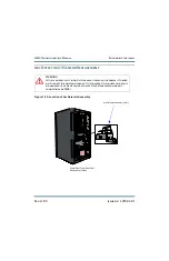
4. Remove and save (6) sets of M5 mounting hardware that support the SCR rectifier
assembly.
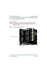
5. Carefully lift and remove the SCR rectifier assembly from the transmitter.
6. Obtain a replacement SCR rectifier assembly (Nautel Part # 207-7055-05).
7. Reverse
to reinstall the new or repaired SCR rectifier assembly.
Ensure all connections are tight, noting the following connections have special torque
values:
• LINE 1, LINE 2 and LINE 3 require 7.6 N-m (67 in-lbs) of torque.
• DC (+) and DC (-) require 6.8 N-m (60 in-lbs) of torque.
• TB1, TB2 and TB3 require 0.45 N-m (4 in-lbs) of torque.
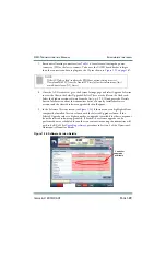
For wiring termination assistance with connections to the SCR rectifier assembly
(A48), check the wiring list in
Section 4, “Wiring/connector lists” on page 4-1
8. Close and lock the rear door, turn AC back on and ensure alarm is cleared.
Summary of Contents for NX50
Page 2: ......
Page 4: ......
Page 8: ...NX50 Troubleshooting Manual Page viii Issue 6 0 2019 04 01...
Page 10: ...NX50 Troubleshooting Manual Page x Issue 6 0 2019 04 01...
Page 108: ...NX50 Troubleshooting Manual Responding to alarms Page 1 98 Issue 6 0 2019 04 01...
Page 153: ...NX50 Troubleshooting Manual Reading Electrical Schematics Page 4 6 Issue 6 0 2019 04 01...
Page 184: ...Issue 6 0 2019 04 01 MD 4 Figure MD 4 NAPI95A 01 Power Module Interface PWB...
Page 188: ...Issue 6 0 2019 04 01 MD 8 Figure MD 8 NAPI106 Remote Interface PWB...
Page 192: ...Issue 6 0 2019 04 01 MD 12 Figure MD 12 NAPI98 RF Drive Distribution PWB...
Page 198: ...Issue 6 0 2019 04 01 MD 18 Figure MD 18 Fan Tray Assembly 207 8133 B1 B2 J1 AIR FLOW AIR FLOW...
Page 201: ...Issue 6 0 2019 04 01 MD 21 Figure MD 21 NAFP106B 01 Directional Coupler A1 DETAIL...
Page 204: ......