


38
All technical manuals are available in PDF format at
tech.napcosecurity.com
Napco iSecure Security System
Hub
by unplugging the AC transformer.
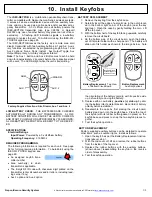
2.
Separate the Go
-
Anywhere Hub housing
. With a flat
head screwdriver, push in the two tabs at the bottom to
unhook, then carefully separate the two parts of the Hub
housing (separating the housing disconnects the battery).
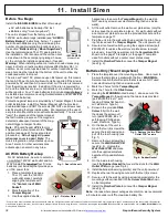
3.
Remove the six (6) screws
that secure the Go
-
Anywhere Hub motherboard PCB to the front housing.
See the arrows in Fig. 2 for screw locations.
4.
The Antenna Board has "peel and stick" adhesive
.
Peel off the protective paper without touching the adhe-
sive.
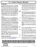
5.
Carefully lift the motherboard
only until you have
enough clearance for the following:
•
With the top edge of the Antenna Board facing
up
, secure the antenna adhesive to the interior plas-
tic, as shown in Fig. 3.
Be careful not to lift the motherboard too far, ensuring all
connections remain secure.
Note:
Be aware the Top Antenna may become discon-
nected; its connectors can easily be re
-
inserted after the
next step.
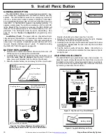
6.
Lower the motherboard
, re
-
aligning all mounting holes.
Gently pull the Antenna Board plug and wire toward the
front
of the motherboard
(this will assist with its connec-
tion to the
ISEC
-
WIFI
module in a future step).
If the Top Antenna disconnects from the motherboard,
be sure to carefully re
-
insert the connections.
7.
Replace the six (6) screws
that secure the Go
-
Anywhere Hub motherboard PCB to the front housing.
See the arrows in Fig. 2 for screw locations.
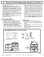
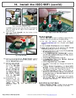
8.
With the ISEC
-
WIFI PC board in hand
, connect the
small
Antenna Board
plug to the
ISEC
-
WIFI
module
socket (see Fig. 4).
The antenna wire should freely rotate while remaining
connected.
Important:
Handle this wire with care; do
not twist, create sharp bends or apply excessive force.
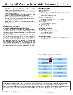
The
ISEC
-
WIFI
allows your
Napco iSecure Go
-
Anywhere
Hub to connect to the Inter-
net by means of a wireless
(Wi
-
Fi) link, eliminating a
wired Ethernet cable connec-
tion.
Note:
The
ISEC
-
WIFI
requires 46mA (standby cur-
rent); refer to the "
STANDBY
-
BATTERY CALCULATION
WORKSHEET
" in this manu-
al to verify that sufficient
power is available.
Prior to opening the
ISEC
-
WIFI
PC board
package or touching
anything inside the
iSecure Go
-
Anywhere Smart
Hub enclosure, discharge any static electricity from your body
or clothing. Use a grounded wrist strap or touch an unpainted,
grounded metal object.
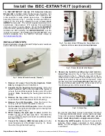
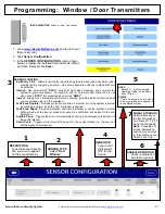
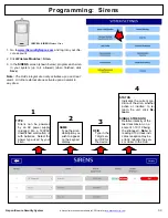
I N S T A L L A T I O N S T E P S
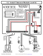
The
Antenna Board
(see Fig. 1) has "peel and stick" adhe-
sive that secures it to the inside of the Go
-
Anywhere Hub
front housing,
with its top edge facing up
). Keep the wire
away from the "Top Antenna" at the top of the Hub.
1.
Remove AC power from the Go
-
Anywhere Smart
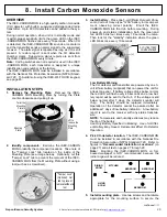
14. Install the ISEC
-
WIFI
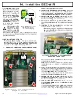
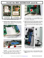
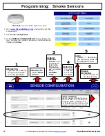
Fig. 2: Arrows show six (6) screws securing the motherboard.
The Top Antenna, is also shown
Top
Antenna
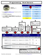
Fig. 3: Carefully lift the motherboard. Note the location of the
Antenna Board's "top edge" (arrow) .
"Top Antenna"
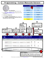
Fig. 1: ISEC
-
WIFI and Antenna
Board (with adhesive).
Arrow points to top edge.
"Antenna
Board"
ISEC-WIFI


