


34
All technical manuals are available in PDF format at
tech.napcosecurity.com
Napco iSecure Security System
12. Install Takeover Module (cont'd)
external power supply). Install
JP13
to power the
FIRE
terminal from internal DC power.
IMPORTANT:
NEVER install wire to terminal
PNL+
when
JP13
is
installed.
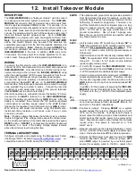
JUMPER DESCRIPTIONS
Jumper Block P2
These "Learn jumpers" are in the
P2
jumper block with posi-
tions numbered, from left to right, as
1
to
6
:
P2 Position 1
-
Shunt position 1 to
DEFAULT
all board flash
memory to the factory default settings (enters RF LEARN
mode). Shunt position 1 before power up; after the
ISEC
-
WL
-
MODULE
is powered, remove jumper from position 1
and the LED marked
LED1
will flash, indicating the unit is
waiting to be learned into the Go
-
Anywhere Hub.
When this learn process completes,
LED1
stops flashing and
remains lit.
P2 Position 2
-
Shunt position 2 to
DISABLE AC
monitoring of
terminals
ACL
and
ACN
. If you wish to disable monitoring of
the AC transformer that powers the DC power supply and
you also wish to enable AC FAIL reporting, shunt this jumper
2. When
P2
is not shunted, the removal of AC will cause the
system to annunciate.
P2 Position 3
-
Shunt position 3 to
DISABLE BATTERY
moni-
toring on the terminal
BATT+
.
P2 Position 4
-
Reserved for future use.
P2 Position 5
-
Reserved for future use.
P2 Position 6
-
Shunt position 6 to start an
END OF LINE RE-
SISTOR LEARN
process for zone terminals
Z1
through
Z8
whereby the value of each normal zone condition is learned
by the system. Within 3 seconds of shunting position 6,
LED3 (at the top of the PC board) will blink to indicate the
learn process is active. This learning process requires that
the zone be wired to a sensor and
ZONE #
jumper (
JP5
to
JP12
; see below) be removed for a short time and re
-
installed. Each normal zone condition is learned by the sys-
tem. If the zone is open, the zone condition will not be
learned. When the zone learning process ends, remove
jumper from position 6; in 3 seconds, LED3 will turn off to
indicate the learning process has ended.
Note:
The factory
default value of the zone terminating resistor is 2.2K
Ω,
and
therefore does NOT require this
END OF LINE RESISTOR
LEARN
process
!
Zone Monitoring Jumpers (JP5 to JP12)
To enable zone monitoring for a zone, place a jumper one of the
8 jumper blocks labeled
JP5
(for
ZONE 1
) through
JP12
(for
ZONE 8
). Each zone 1
-
8 is assigned to terminals
Z1
through
Z8
, respectively.
Notice each jumper block labeled
JP5
through
JP12
contains
vertical 4 pins:
•
FIRE
(top two pins): Selected zone reports as a Fire trans-
mitter (for example, a model
ISEC
-
SMOKE
detector).
•
CO
(middle two pins): Selected zone reports as a carbon
monoxide (model
ISEC
-
CARBON MON
) transmitter.
•
BURG
(lower two pins): Selected zone reports as a Bur-
glary window / door transmitter (model
ISEC
-
DW
-
XMITTER
) with one point (i.e. reports the zone change
from "normal" to "open").
Takeover Module Tamper
The tamper switch on the PC board is always active to monitor
the opening of the front cover. Cut jumper
JPR1
to enable the
rear tamper switch to monitor the removal of the
ISEC
-
WL
-
MODULE
from the wall or other mounting surface. When the
unit is in operation and a tamper switch is triggered, an
E15
tamper trouble will be generated for the associated zone:
•
ISEC
-
WL
-
MODULE # 1 tamper generates
E15
-
93
•
ISEC
-
WL
-
MODULE # 2 tamper generates
E15
-
94
•
ISEC
-
WL
-
MODULE # 3 tamper generates
E15
-
95
•
ISEC
-
WL
-
MODULE # 4 tamper generates
E15
-
96
SPECIFICATIONS
Electrical Ratings
Input Power:
12.5
-
7.5VDC, 15mA + Zone loop current times
the number of zones enabled + PGM current. Max
current = 65mA.
Zone Loop current:
4.7mA nominal, 5.5mA when shorted.
Maximum Zone Loop Resistance:
300 ohms.
2.2K End of line resistor
(part number EOL2.2K required in Fire
applications).
Output Power:
PGM Output (Active low):
5mA, 12V. Connect only to power
-
limited circuits less than 14VDC. Use only in Burglary
applications.
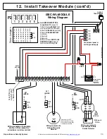
BATTERY MONITORING
To enable battery monitoring, remove the shunt across
P2 Posi-
tion 3
.
Battery Wiring:
1.
Disconnect the battery of the Hub to be taken over and un-
plug its AC transformer.
2.
Cut the control panel's red battery flying lead approximately
3 inches from the battery terminal.
3.
Strip both sides of the cut flying lead to expose wire.
4.
Inside the panel housing, using a suitable wire connector,
crimp both sides of the stripped flying battery lead and one
side of the supplied EOLR2.2K.
5.
Using a suitable connector, crimp the remaining side of the
EOLR2.2k to the wire that extends outside the panel hous-
ing to the ISEC
-
WL
-
MODULE "
BATT+
" terminal.
6.
Ensure the wires connected to the battery are separated by
at least 1/4 inch from any non
-
power limited wire inside the
panel housing.
Enable AC Fail Monitoring:
•
Remove shunt across header
P2 Position 2
to enable AC
monitoring.
•
For the Hub to be taken over, connect the AC terminal to the
ISEC
-
WL
-
MODULE "
ACL
" terminal.
continued


