


Napco iSecure Security System
All technical manuals are available in PDF format at
tech.napcosecurity.com
37
13. Install the ISEC
-
2WF
-
MOD (cont'd)
PROGRAMMING
After the
ISEC
-
2WF
-
MOD
module is installed, program the
Go
-
Anywhere Hub using the iSecure Cloud Web Portal:
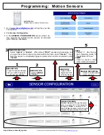
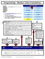
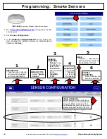
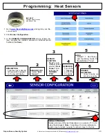
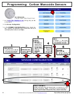
1.
Log into the iSecure Cloud Web Portal at
www.iSecureByNapco.com
as a Dealer (click
Dealer
Login
).
2.
Click
Sensor Configuration
.
3.
In zone 7 or in zone 8, in the
Sensor Type
column, se-
lect
Wired Fire
.
ISEC
-
2WF
-
MOD INSTALLATION
If the Go
-
Anywhere Smart Hub enclosure is not already
open, open the enclosure as directed on page 10, step 3.
Remove all A/C and battery power and install the
ISEC
-
2WF
-
MOD
into the iSecure Hub main PCB as follows:
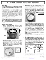
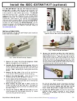
1.
Insert the plastic Standoff into the bottom of the
ISEC
-
2WF
-
MOD
(Fig. 1).
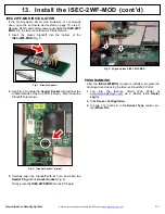
2.
Use Fig. 2 to locate the
Header Socket
located near the
middle left side of the Hub PCB (circled). Also locate the
Standoff hole (arrow).
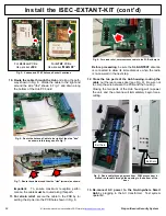
3.
Carefully align the Standoff with its hole, and align the
Header Plug
with its
Header Socket
(Fig. 3).
Firmly press the
ISEC
-
2WF
-
MOD
into the PC board.
Fig. 1: Standoff (arrow)
Fig. 2: "Header Socket" (circled)
Fig. 3: Align and insert ISEC
-
2WF
-
MOD


