NAPCO iSecure Installation & Programming Instructions Download Page 17

Napco iSecure Security System


All technical manuals are available in PDF format at 

tech.napcosecurity.com


17


when mounted above sinks, when used in residential car 

garages,  and  in  other  small,  acoustically  live  rooms  and 

rooms  where  multiple  sound  can  reflect  and  eventually 

duplicate the glass

-

break frequency pattern. For occupied

-

area glass

-

break protection in such applications, the use of 

shock sensors is recommended.


3.


Installing  the  unit  on  24

-

hour  loops  will  increase  false 

alarms.  The  ISEC

-

GLASSBREAK  is  recommended  for 

perimeter  loops  and  is  designed  to  function  without  false 

alarms  in  occupied  areas.  On  a  24

-

hour  loop,  which  is 

armed all day, all night, every day, the false alarm technol-

ogy will be pushed to its limit since some sounds in some 

conditions can duplicate the points on the glass

-

break pat-

tern  that  the  unit  detects.  Install  the  unit  on  a  perimeter 

loop, which is armed whenever the door and window con-

tacts are armed. For occupied

-

area installations, the ISEC

-

GLASSBREAK's  false

-

alarm  immunity  is  best  in  rooms 

with only moderate noise.


4.


The unit detects the shattering of glass. As with all glass

-

break  detectors,  it  may  not  consistently  detect  cracks  in 

glass or bullets that break through the glass or break out 

the glass. Glass

-

break detectors should always be backed 

up by interior protection.


TESTING


Preliminary


Use a Sentrol Model 5709

-

C hand

-

held tester (available sepa-

rately) to place the detector into its test mode and for all func-

tional testing.


Set the tester for tempered glass. Holding the tester speaker 

directly  over  the  sensor,  activate  the  tester.  The  detector  will 

go into alarm (LED will come on for about 4 seconds), then go 

into the test mode for one minute. While in the test mode, the 

detector's  LED  will  blink  continuously.  Extend  test

-

mode  time 

by firing the tester at least once a minute.


Testing the Sensor


The  5709

-

C  tester  has  a  setting  for  each  type  of  glass.  The 

tester should always be set for Tempered or Laminated glass 

(either  is  correct  and  both  have  the  same  range)  unless  the 

installer is certain that the glass to be protected is plate glass.


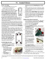
Holding the tester near the surface of the glass, aim the tester 

at the detector and hold down test button. If drapes or blinds 

are  present,  test  with  the  hand

-

held  tester  behind  the  closed 

drapes  or  blinds  (do  not  use  detector  with  heavy  or  lined 

drapes).  If  the  detector  is  mounted  on  the  same  wall  as  the 

glass, point the tester at the opposite wall.


If the LED on the detector comes on for about 4 seconds when 

the tester is triggered, the glass is within detection range. If the 

LED does not come on but just continues to blink, reposition 

the  detector  closer  to  the  windows  and  retest.  This  may  re-

quire  the  use  of  additional  detectors  in  order  to  achieve  the 

desired coverage. In the unlikely event that the detector does 

not respond within its stated range of coverage, check the bat-

tery in the tester; a new battery will likely restore range.


The ISEC

-

GLASSBREAK detector will automatically revert to 

its  normal  operating  mode  approximately  1  minute  after  the 

last test.


Note:

  Room  acoustics  can  artificially  extend  the  range  of  a 

glass

-

break  sensor.  The  specified  range  of  the  ISEC

-

GLASSBREAK  detector  has  been  established  for  worst

-

case 

conditions.  While  the  sensor  will  likely  function  at  additional 

range, it may miss a minimum output break, or room acoustics 

may  be  changed  at  some  future  time,  bringing  sensor  range 

back into normal 20' (6m) conditions. Do not exceed the rated 

range of the sensor, regardless of what the tester shows.


Test

-

Mode Operation


The  ISEC

-

GLASSBREAK  ignores  most  false  alarm  sounds, 

including  glass  break  testers.  In  order  to  test  the  ISEC

-

GLASSBREAK detector, a test mode is used. In its test mode, 

sensor processing of the glass

-

break pattern in the upper and 

lower frequencies is disabled, thus the sensor is listening only 

for the midrange frequencies, which the tester produces. It is 

the midrange frequencies that determine sensor range.


In the normal operating mode, the LED does not blink unless 

the sensor hears a loud sound. In normal operation, the ISEC

-

GLASSBREAK detector will not be tripped by the tester unless 

the tester is held right up against the sensor.


Note:

 Each time the detector goes into alarm, it also goes into 

the test mode for one minute.


Hand

-

Clap Test


The ISEC

-

GLASSBREAK can be tested by the installer or the 

end  user  while  in  its  normal  mode  simply  by  clapping  loudly 

under the sensor. The LED will blink twice, but the detector will 

not trip. This verifies visually that there is power to the detector 

and that the microphone and circuit board are functioning. The 

hand

-

clap activation is momentary so there is no appreciable 

effect on battery life.  


See page 46 for full programming information.  
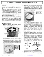
 

4.  Install Glass

-

Break Sensors (cont'd)


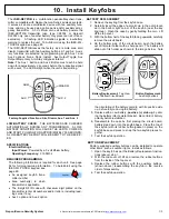
COVERAGE AREA ALL GLASS 

ADDITIONAL COVERAGE AREA 

FOR PLATE GLASS 

Fig. 3. Typical coverage pattern for ceiling

-

mounted units.


Fig. 4. Testing the sensor.


Summary of Contents for iSecure

Page 1: ...Napco iSecure Security System All technical manuals are available in PDF format at tech napcosecurity com 1 NAPCO 2021 WI2240ALF 6 21...

Page 2: ...It is subject to change without notice Companies names and data used in examples herein are fictitious unless otherwise noted Napco assumes no responsibility for incor rect information this manual ma...

Page 3: ...Install the ISEC ZWAVE 40 Install the ISEC EXTANT KIT optional 41 Go Anywhere Smart Hub Icons 43 PROGRAMMING Programming Keypads Touchscreens 44 Programming Motion Sensors 45 Programming Glass Break S...

Page 4: ...382LF Hub tamper in stallation instructions included All Kits support up to six 6 ISEC WL KEYPADs and or ISEC WL TOUCHs combined When the Go Anywhere Hub is connected to a network with a Wi Fi access...

Page 5: ...gin Refer to the OI404LF card and enter your Dealer User ID Password and Radio ID iSecure LTE ID Click Submit D Click General Settings and in the Master Security Code field enter the Master Code also...

Page 6: ...within 15 minutes of checkout With iSecure a new subscriber account will automatically be created A Dealer User ID and temporary Password will be emailed to you the dealer upon activation This tempora...

Page 7: ...r the first time In the confirmation popup click Yes download to send all changes to the Go Anywhere Smart Hub Network MAC Unique Media Ac cess Control identifier assigned to the integral network inte...

Page 8: ...to enable the IP path of the integral dual path radio communicator this selection is available depending on plan purchased Configuration Type Click the Configuration Type pull down to select the re po...

Page 9: ...e iSecure Cloud Web Portal Note Radio will reboot after the successful download of new IP configurations IMPORTANT Some police and or fire departments require alarm permits contact each department do...

Page 10: ...or 5AH battery not supplied observing polarity secure battery with Velcro strap 7 Remove the plastic protective film from the face of the Go Anywhere Hub STAND ALONE INSTALLATIONS If placing on a she...

Page 11: ...s speakers or a mechanical bells this terminal and BELL Any self contained external siren requiring a 12V supply can be connected When connecting a mechanical bell it must be supervised using a 2 2k O...

Page 12: ...o place 4 Drill the two keypad mounting holes four holes with the IBR TOUCH WL in the mounting surface When mounting to hollow drywall or similar surface we recommend using wall anchors or similar har...

Page 13: ...security system keypad tap Keypad Only jump to step 6 To include video camera and Z Wave functions tap Full Functionality 4 5 Add the IBR TOUCH WL Tablet Kit 3 Only The steps below are the only steps...

Page 14: ...dministrator account User ID and Password and tap Finish 10 Upon connection to the Internet based ac count for the iSecure system the resulting keypad shown in step 12 will be configured for the payme...

Page 15: ...ON The ISEC MOTION is an advanced PIR sensor designed for use with Napco s wireless receivers The unit is powered by two sup plied 3 volt lithium batteries estimated battery life 3 years If bat tery v...

Page 16: ...as a template to mark mounting holes on the wall The sensor must be in direct line of sight of all windows being protected Reliable detection cannot be expected around cor ners in other rooms etc For...

Page 17: ...ector is mounted on the same wall as the glass point the tester at the opposite wall If the LED on the detector comes on for about 4 seconds when the tester is triggered the glass is within detection...

Page 18: ...DESCRIPTION The ISEC DW XMITTER is a low profile window door transmitter designed for use in Napco iSecure wireless systems Used with the supplied magnet the transmitter functions as a window door se...

Page 19: ...location to mount the ISEC SMOKE Note Mounting the ISEC SMOKE on foil backed wallpaper is NOT recommended because the radio range will be reduced The ISEC SMOKE is a high quality photoelectric smoke...

Page 20: ...e correct zone on the Hub and that the correct report is sent to the central sta tion NOTE Smoke detectors are not to be used with detector guards unless the combination has been evaluated and found s...

Page 21: ...utomatically exit this mode after 5 minutes Note If smoke is still present in the chamber after exiting Silence mode the detector will go into alarm again IMPORTANT Use proper polarity when installing...

Page 22: ...eratures Also do not locate alarm in front of air conditioners heating registers or other locations where normal air circulation will keep smoke from entering the detector Installing smoke detectors i...

Page 23: ...onitor and annunciate low battery Coding switches are not required or used in the ISEC HEAT Each transmitter is assigned a unique identification code number at the factory The transmitter is powered b...

Page 24: ...ystem Test system with unit mounted If the system is monitored notify the central station of the impending test The rate of rise feature may be tested by a quick applica tion of heat from any convenie...

Page 25: ...ta or Sanyo type 123A battery in its compart ment observing correct polarity Enroll the ISEC CARBON MON into the Hub before mounting During power up and status initialization both the green and red LE...

Page 26: ...ss and hold the re cessed TEST button for approximately 2 seconds The detector will temporarily go into alarm and the red LED will illuminate b Within a few seconds the green LED will start to blink r...

Page 27: ...e equipment manufacturer s doc umentation or contact the manufacturer s directly for more information about how the equipment can leak carbon monoxide into the premises Ensure all motor vehicles are n...

Page 28: ...installation instructions in their entirety be fore installing the ISEC CARBON MON detector Leave these instructions with the owner user of the detector The ISEC CARBON MON is intended for use in ind...

Page 29: ...detector indicates an end of life condi tion whichever comes first CO detectors are not a substi tute for designated life safety devices Napco does not war rant or imply in any way that a CO detector...

Page 30: ...uit board no more than 45 degrees see Figures 1 and 2 to allow removal of batteries from the bottom circuit board 3 Slide the bottom battery out and away from the circuit board Figure 3 Top View of Bo...

Page 31: ...to which transmitter is applicable The 6 digit RF ID code with checksum digit printed on the transmitter enter all numbers and or letters including lead ing zeros if any Aux 1 option and Aux 2 option...

Page 32: ...t 3 Use the supplied double backed tape to secure the Tamper Magnet to the wall do NOT use any screws near electrical wiring that runs inside walls 4 At the wall outlet remove the wall cover plate scr...

Page 33: ...on If RESET is not pressed the battery trouble will self restore in 4 hours if the battery voltage always remains above the minimum level during this time TERMINAL DESCRIPTIONS Configure all inputs an...

Page 34: ...through JP12 for ZONE 8 Each zone 1 8 is assigned to terminals Z1 through Z8 respectively Notice each jumper block labeled JP5 through JP12 contains vertical 4 pins FIRE top two pins Selected zone rep...

Page 35: ...UMPER ZONE 1 FIRE CO BURG SET JUMPER ZONE 7 FIRE CO BURG SET JUMPER ZONE 8 FIRE CO BURG P2 1 2 3 4 5 6 BAT BAT DC DC 12 18VAC TRANSFORMER Control panel power or auxiliary power supply FIRE CO BURG ZON...

Page 36: ...zone 7 FIRE PR Connects to the positive terminal of the two wire smoke sensor Z8 Connects to the negative terminal of the two wire smoke sensor zone 8 Connect the 2 wire smoke detectors to the Go Anyw...

Page 37: ...MOD INSTALLATION If the Go Anywhere Smart Hub enclosure is not already open open the enclosure as directed on page 10 step 3 Remove all A C and battery power and install the ISEC 2WF MOD into the iSe...

Page 38: ...t secure the Go Anywhere Hub motherboard PCB to the front housing See the arrows in Fig 2 for screw locations 8 With the ISEC WIFI PC board in hand connect the small Antenna Board plug to the ISEC WIF...

Page 39: ...orks pull down find and select the SSID name of the customer s network Upon selection the Security Type and Selected Network fields will automatically populate Type the Password of the customer s Wi F...

Page 40: ...our body or clothing Use a grounded wrist strap or touch an unpainted grounded metal object If replacing an older version of the ISEC ZWAVE first down load the latest version of the Z Wave firmware at...

Page 41: ...e front LED Faceplate to the front housing 4 Remove the LED Faceplate From the front of the housing pull out the LED Faceplate to remove 5 On the inside of the LED Faceplate remove the screw that secu...

Page 42: ...lose the two parts of the Hub housing routing the cable out the rear access door see Fig 9 Be sure not to crimp the wire between the PCB and the housing Closing the two parts of the Hub housing will r...

Page 43: ...Receiver trouble due to excessive radio noise in area Try relocating the Smart Hub Otherwise call for service Rapid Flicker Transmissions in progress Flashing 900MHZ peripheral download Status Off No...

Page 44: ...he ISEC WL TOUCH press and hold the appropriate FIRE AUX or PANIC button respectively see the User s Guide for details By default Emergency Buttons are ena bled for all keypads to disallow their use s...

Page 45: ...R FUNCTION Select Instant or Interior When armed STAY usually when sleeping and you want the motion to ignore movement within the home select Interior If you want the sensor to immediately trigger an...

Page 46: ...it sensor ID for the device 4 DESCRIPTION Type the sensor descrip tion you wish to appear on the keypad display AREA Default 1 See the key pad Operating Guide for the definition of Area SENSOR FUNCTIO...

Page 47: ...or For example use for an interior door that will be in use when armed STAY but protected when armed AWAY Instant Allows for an immediate alarm when activated providing instant protection while you or...

Page 48: ...N Type the sensor descrip tion you wish to appear on the keypad display SENSOR TYPE Select Smoke Sensor SENSOR FUNCTION Smoke is au tomatically se lected when Smoke Sen sor is selected as the SENSOR T...

Page 49: ...on the keypad display SENSOR TYPE Select Heat Sensor SENSOR FUNCTION Heat is auto matically select ed when Heat Sensor is se lected as the SENSOR TYPE SENSOR ID Type in the 7 digit sen sor ID for the...

Page 50: ...or DESCRIPTION Type the sensor descrip tion you wish to appear on the keypad display SENSOR TYPE Select Carbon Monoxide SENSOR FUNCTION CO Alarm is automatically selected when Carbon Mon oxide is sele...

Page 51: ...the following Instant Allows for an immediate alarm when the panic button is pressed providing instant protection 24Hr Zone Audible Provides protection at all times whether or not the system is armed...

Page 52: ...e Select to disable the designated key Key 3 and or Key 4 Panic Pressing the designated key causes the siren to sound and sends a panic report to the central station Instant Pressing the designated ke...

Page 53: ...in any Area ISEC WL SIREN Wireless Siren TYPE Sirens can be powered by an AC power supply plugged into a 120VAC unswitched wall outlet or with batteries Select the power type used by your siren NAME...

Page 54: ...ired zone to the RF ID of the supervised 900MHz wireless zone up to 8 zones for each ISEC WL MODULE In the TAKEOVER screen shown below for the Takeover Module added previously program each column as d...

Page 55: ...umn 3 To add a new Code click in a blank USER CODES field and enter the new User Code up to 6 digits To erase or change an existing Code simply clear or re enter the User Code 4 Add a check to either...

Page 56: ...ng to establish a connection if this code is forgotten the Master Security Code of the particular Go Anywhere Hub can be used in its place Dealer Keypad Programming Code This code is left blank in the...

Page 57: ...at you wish to be used in text and email notification messages to help you identify the iSecure system installation Video Security Z Wave Remote Access Check to enable access to each service from the...

Page 58: ...can also be configured to allow Wi Fi con nections to only specific MAC Addresses Displays the MAC Address of the Go Anywhere Hub in an easy to copy field should it be needed Users Displays the USER I...

Page 59: ...sor within the Go Anywhere Hub that controls the radio communications between the Hub and the wireless de vice s Other iSecure Cloud Web Portal Screens cont d RadioHardware Version refers to the versi...

Page 60: ...relocate the Go Anywhere Smart Hub or the device so they are in closer proximity E 05 NN Transmitter Low Battery When an RF device has a weak battery an error E 05 appears The NN is a two digit number...

Page 61: ...top as shown in the image Note Never use the jumper position N A Use hearing protection siren is rated at 85dBA Do not apply AC power when rear cover is open 1 Remove AC and batteries 2 Remove jumper...

Page 62: ...h the same type as specified above Use of other types may present a risk of fire or explosion Nev er recharge or disassemble a battery or dispose of in fire E06 NN Receiver Response Failure Call insta...

Page 63: ...TER When the test is initiated data is transferred back and forth be tween the keypad and Hub When finished the signal levels of both the keypad and Hub are displayed and a beep is heard in the sequen...

Page 64: ...Secure system might be interfering with the system to be installed the ISEC WL KEYPAD can be used as a scanner to scan for the presence of other nearby iSecure radio signals and determine if the nearb...

Page 65: ...unication link between the Hub and the ISEC WL TOUCH keypad was interrupted If Out of System this field will count down AutoEnroll This feature is a quick and easy way to enroll wireless devices into...

Page 66: ...w E02 00 will appear in the display indicating a low battery condition Allow 24 hours for the battery to recharge DISPLAY SYS TRBL Displays all system error codes troubles LOW BAT TERY AC POWER LOSS e...

Page 67: ...pertinent information where necessary depending upon the event TO ARM IN 1 4 HRS Use this function to a delay programmed auto arming up to 4 hours 15 minutes or b initiate auto arming in 4 hours 15 mi...

Page 68: ...scribed below tap Config ure otherwise tap Continue to App to return to the Home Screen or Test Again to repeat the test See page 13 for step by step instructions to help guide you through the Wiz ard...

Page 69: ...1 3 5 7 10 15 and 20 minutes BSSID used to LOCKDOWN IBRIDGE Tap to enter a new broadcast SSID named BSSID in this menu to be stored in the touchscreen s memory to be used by default when the touchscre...

Page 70: ...then connect power to the camera Do you wish to proceed with Wire less Camera Configuration 1 The camera must be powered and wirelessly con nected to the network before proceeding 2 Tap Yes to procee...

Page 71: ...wish to disallow customer changes to the home automation Z Wave system unchecking disabling this setting disables the User Settings menu feature named Automation Management z wave Converse ly check t...

Page 72: ...hours with network connection 32 hours ISEC KIT2 Battery Standby Hours 12V 4AH battery No network connection 25 hours with network connection 24 hours 12V 5AH battery No network connection 32 hours w...

Page 73: ...RT HUB In cludes up to 80 wireless zones in 1 or 2 discrete Areas with keypad bus and other optional con nections Kits with the suffix V use the Verizon network A use the AT T network IBR TOUCH WL Sma...

Page 74: ...s re ceivers The ISEC MOTION is powered by two supplied 3 volt lithium batteries estimated battery life 3 years When battery voltage drops below normal a low battery report will be sent to the re ceiv...

Page 75: ...Wireless Siren Mounting Template Slide Screw Use with battery powered units only Magnet 1 5 8 Align this centerline with Wall Socket 7 16 Magnet Screws 2 Use with battery powered units only Center Lin...

Page 76: ...76 All technical manuals are available in PDF format at tech napcosecurity com Napco iSecure Security System Notes...

Page 77: ...rews 2 Use with battery powered units only Center Line of Wall Socket 5 1 4 Screw Hole Tab Align this centerline with Wall Socket This template shows the unit plugged into the bottom receptacle but ei...

Page 78: ...78 All technical manuals are available in PDF format at tech napcosecurity com Napco iSecure Security System ISEC WL MODULE Takeover Module Wiring Diagram...

Page 79: ...Napco iSecure Security System All technical manuals are available in PDF format at tech napcosecurity com 79 iSecure Hub Wiring Diagram LA3550A3...

Page 80: ...he product Seller s warranty as hereinabove set forth shall not be enlarged diminished or affected by and no obligation or liability shall arise or grow out of Seller s rendering of technical advice o...

Reviews: