


30
All technical manuals are available in PDF format at
tech.napcosecurity.com
Napco iSecure Security System
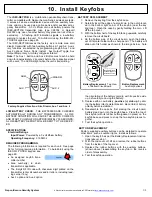
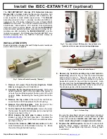
9. Install Panic Button
GENERAL DESCRIPTION
The ISEC
-
PANIC Panic is an single function pendant / key-
chain transmitter compatible with the NAPCO iSecure security
system. The ISEC
-
PANIC serves as an emergency device for
use as a police panic and/or auxiliary emergency transmitter.
Two replaceable Energizer 386 1.5V silver oxide cells power the
transmitter. A flashing LED signals a low
-
battery warning. To
operate, simply press the button momentarily until the red LED
lights.
Note:
When the button is pressed, the ISEC
-
PANIC will
transmit the respective signal to the Central Station, if so pro-
grammed. The LED lights while the unit is transmitting. See
page 51 for full "
Sensor Configuration
" programming infor-
mation.
Low
-
Battery Check:
The power cells are checked automati-
cally during any transmission. A low
-
battery condition causes the
LED to turn on for twice the normal time, then start pulsing about
once every 1.5 seconds; a low
-
battery report will be sent to the
receiver. Replace batteries every 3 years. To AutoEnroll using
the ISEC
-
WL
-
TOUCH keypad, see page 65.
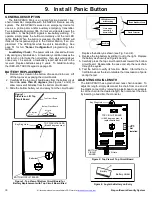
BATTERY REPLACEMENT
1.
Remove the screws on the bottom of case and turn over. Lift
off the top cover, exposing the circuit boards.
2.
Carefully
lift the top circuit board away from the bottom circuit
board
no more than 45 degrees
(see Figures 1 and 2) to
allow removal of batteries from the bottom circuit board.
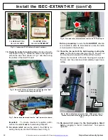
3.
Slide the bottom battery out and away from the circuit board.
Figure 3: Top View of Bottom Circuit Board for
Battery Replacement with Top Circuit Board lifted
Key Ring Hole
TOP CIRCUIT BOARD
(lifted 45 degrees max.)
Batteries
BOTTOM CIRCUIT BOARD
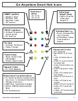
Figure 2: Top View of Top Circuit Board
Key Ring Hole
Lift Here
JP1:
Not
Installed
BOTTOM
CIRCUIT
BOARD
TOP CIRCUIT BOARD
(Lift 45 degrees max. to
replace batteries)
Replace the battery as shown (see Fig. 3 and 4).
4.
Replace the top battery by sliding it out to the right. Replace
the battery as shown (see Figures 3 and 4).
5.
Carefully press the top circuit board back toward the bottom
circuit board. Reassemble the case and slip the neck chain
through the eyelet.
6.
Test the button to verify its function.
Note:
Inform the Cen-
tral Station about the test or disable the transmission of panic
during the test.
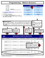
ADJUSTING CHAIN LENGTH
The ISEC
-
PANIC has a plastic bead neck chain included. To
adjust its length, simply disconnect the chain from one end of
the plastic connector by removing a plastic bead, use scissors
to cut the chain to the desired length, then reconnect the chain
by inserting a bead into the connector.
Key Ring
Press button
momentarily to
transmit alarm
LED lights when unit
is transmitting
Plastic Bead Neck Chain
Plastic Connector
Top Circuit Board
Bottom Circuit Board
45 degrees
max.
Batteries
Figure 1:
Side View
-
Lift Top
Circuit Board
Figure 4: Angle the Battery on Entry
Battery
Battery Holder
+


