


Napco iSecure Security System
All technical manuals are available in PDF format at
tech.napcosecurity.com
33
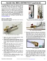
12. Install Takeover Module
DESCRIPTION
The
ISEC
-
WL
-
MODULE
is a "takeover module", used to convert
an existing wired security system to wireless. The
ISEC
-
WL
-
MODULE
will convert a total of 8 wired zones and convert them
into 8 supervised wireless 900MHz zones. For example, if you
have existing wired security system sensors such as motion de-
tectors, glass break sensors and door/window transmitters, you
can use the existing wiring for each of these devices and convert
them into iSecure system wireless zones. Up to 4
ISEC
-
WL
-
MODULE
s are allowed with each Go
-
Anywhere Smart Hub.
Note:
For existing 2
-
wire smoke detectors, the
ISEC
-
2WF
-
MOD
2
-
Wire Fire Sensor Module
may be used if the detectors are
compatible (see page 36 for the list of compatible detectors and
additional information).
Note:
Pressing the keypad
RESET
but-
ton sends an updated zone status and module status from the
ISEC
-
WL
-
MODULE
to the Hub. In addition,
LED1
turns on for
10 seconds. Remove power from smoke detectors for 10 sec-
onds to reset. See page 54 for full programming information.
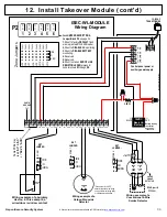
WIRING
In general, the first step for wiring the
ISEC
-
WL
-
MODULE
is to
connect all of the Zone data wires to a mounted and
unpowered
ISEC
-
WL
-
MODULE
. Only after all zone and other wiring is con-
nected should you then power the
ISEC
-
WL
-
MODULE
using
either the existing wired 12VDC power connections from the ex-
isting security control panel or by an auxiliary power supply.
Connect the high side (positive) of each wired zone to its own
screw terminal, labeled
Z1
,
Z2
, etc. on the
ISEC
-
WL
-
MODULE
terminal strip. Note that several sensors can be wired to a single
zone provided they are wired in series. Connect the low side
(negative) of each wired zone to any of the ground terminals
(labeled
GND
next to each zone terminal).
After all zone wires are connected, connect the battery 12V posi-
tive lead to the
BATT+
terminal on the
ISEC
-
WL
-
MODULE
.
Connect the battery ground lead to any
GND
terminal. After the
battery is connected, then connect the 12V positive regulated
control panel (or auxiliary supply) power to the
+12V
terminal
followed by the negative ground connection to any
GND
terminal.
Wire all zone and power connections using 18
-
22AWG wire.
Install end
-
of
-
line resistors on all zones, even if one or more
zones are not used.
Note:
If battery voltage falls below the minimum level, a battery
trouble is triggered; if the voltage climbs above the minimum lev-
el, the trouble will restore 30 seconds after pressing the keypad
RESET
button. If
RESET
is not pressed, the battery trouble will
self
-
restore in 4 hours if the battery voltage always remains
above the minimum level during this time.
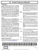
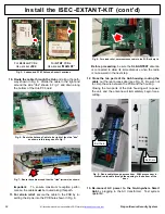
TERMINAL DESCRIPTIONS
Configure all inputs and outputs using the Management Center
(the Napco "NOC" located at
www.iSecureByNapco.com
). Lo-
cated at the bottom of the PC board, the 20 terminals are:
EARTH
....
This optional earth ground terminal provides protection
from high
-
voltage transients (for example, nearby light-
ning discharges induce high
-
voltage transients into the
field wiring of electronic equipment). Therefore, con-
nect this terminal to a metal cold
-
water pipe or a long
steel (or copper) ground rod driven deeply into the
earth. Do not use a gas pipe, plastic pipe or AC
ground connections. Use at least 16
-
gauge wire.
Make the run as short and direct as possible, without
any sharp bends in the wire.
16VAC
SUPV
......
(Left terminal; some PC boards may indicate "
AC
" or
"
ACL
") Non
-
polarized 16VAC terminal used for moni-
toring AC (
for supervision only, not power
). Con-
nect to AC power source terminal (power supply or
Hub power).
(Right terminal; some PC boards may indicate "
AC
" or
"
ACN
") Non
-
polarized 16VAC terminal used for moni-
toring AC. Connect to AC power source terminal
(power supply or Hub power).
+12V
........
+12 volts DC to power the
ISEC
-
WL
-
MODULE
. Con-
nect this terminal to the Hub
PGM (+)
terminal or to the
+12VDC terminal of the dedicated power supply
GND
‒
......
Common ground terminal for all sensors (all
GND
ter-
minals are electrically equivalent). Therefore, connect
the low side (negative) lead of each wired zone to the
GND
terminal next to each zone terminal (labeled
Z1
,
Z2
, etc.).
In addition, for the purpose of powering the
ISEC
-
WL
-
MODULE
, connect this terminal to the Hub
(‒)
Auxilia-
ry Power or to the
(‒)
12VDC of the dedicated power
supply.
Z1+
-
Z8+
........
Connect the high side (positive) lead of each wired
zone to its own screw terminal, labeled
Z1
,
Z2
, etc., for
each zone 1 through 8, respectively.
F PWR
.....
Fire Reset (output). Pressing
RESET
on a system
keypad causes this output to change state (on to off,
off to on) for 10 seconds. Typically used to create a
power output for latching 4
-
wire smoke detectors and
similar devices that require power to be removed for
reset. May also be used on door latches that normally
require power, thus power is removed on a "Fire
Alarm" event.
BATT+
.....
Optional connection to the existing Hub b termi-
nal (or + terminal of the power supply) for power super-
vision. Place shunt across
JP3
to enable supervision.
PNL+
.......
Ex12VDC power input used to power the
FIRE
terminal (described above). Remove jumper
JP13
when
FIRE
output is powered by an external power
source (for example, wired to the DC+ output of an
Some PC boards may
indicate "
AC
" and "
AC
"
or "
ACL
" and "
ACN
"
EARTH
+12V
GND
‒
Z1+ Z2+
GND
‒
Z3+ Z4+
GND
‒
Z5+ Z6+
GND
‒
Z7+ Z8+
GND
‒
PNL+
16VAC SUPV
F PWR
BATT+
continued


