


32
All technical manuals are available in PDF format at
tech.napcosecurity.com
Napco iSecure Security System
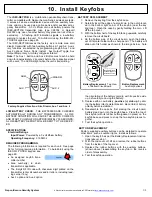
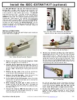
11. Install Siren
Before You Begin
Install the
ISEC
-
WL
-
SIREN
in either of two ways:
•
AC with batteries as backup if AC lost
•
Batteries only ("mount anywhere")
The unit is shipped from the factory with the
120VAC wall outlet prongs installed (see "
AC With
Battery Backup
" instructions, below). To power
the siren with batteries only, thus increasing the
number of possible installation locations, skip to
the section "
Batteries Only ('Mount Anywhere')
".
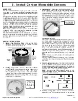
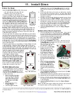
Use the template (page 75 or 77) appropriate for
the installation. We recommend the unit be orient-
ed as shown in the accompanying image; howev-
er, the unit can be installed upside down if needed.
Warning:
When installing outdoors,
locate in shaded areas only,
never in direct sun
(extreme temperatures affect battery life). In
addition, do not mount upside down for outdoor locations as the
weep hole must be located at the bottom of the unit to allow any
condensed water to drip out.
The siren will "learn" AC presence upon first power up; this means
that an AC Power Failure trouble will only be reported if the siren is
powered by AC and then AC power is lost or if the siren is removed
from the wall power socket. In addition, if the siren is powered by
AC and the batteries are low (or not installed), a low battery trouble
will be reported. Four 'C'
-
size batteries (not included)
must always
be installed (we recommend using Duracell alkaline; never use less
than 4 fresh batteries).
Protection against tamper is provided by a Tamper Magnet; for wall
outlet installations, install this Tamper Magnet with the provided
double
-
sided tape and NOT the screws (DO NOT use screws near
electrical wiring that runs inside walls). We recommend the use of
ear protection should the siren activate inadvertently. The siren will
"learn" the presence of the tamper magnet
the first time the presence of the magnet is
detected; subsequent removal of the mag-
net will trigger a tamper trouble.
Note:
PC board header
JP2
is factory
shipped with a shunt placed in the "
Store
"
position (see page 61 for reset and test
procedures).
Do not apply AC power
when rear cover is open!
Note:
The
Hub's integral siren only activates upon an
Area 1 alarm. All other external sirens
activate upon an alarm in any Area.
AC With Battery Backup
For AC installations, be sure to select an
un
-
switched 120VAC wall outlet and AL-
WAYS install the
required
four 'C'
-
size
batteries (not included) that provide pow-
er if AC power fails.
1.
Place a template (see page
75 or 77) over the 120VAC
wall outlet socket, carefully
aligning the template with
the "
Center Line of Wall
Socket
".
2.
Mark the location of the
Tamper Magnet
.
3.
Use the supplied double
-
backed tape to secure the
Tamper Magnet
to the wall (do
NOT use any screws near electrical wiring that runs inside
walls).
4.
At the wall outlet, remove the wall cover plate screw (only the
screw; keep the cover plate in place). For wall outlets without
a center cover plate screw, use the provided bracket and the
template on page 77.
5.
Plug the unit into the wall outlet, being certain the siren hous-
ing is placed over the
Tamper Magnet
. The unit powers up*.
6.
Secure siren to wall outlet by using the supplied screw (part
#SC206LF) to replace the wall cover plate screw removed
previously. Insert this new screw into the
Screw Hole Tab
shown on the page 75 template (or the page 77 template
used for outlets without a center cover plate screw).
7.
Install the
Finisher Plate
to conceal the
Tamper Magnet
(see Fig. 2).
Batteries Only ('Mount Anywhere')
1.
Place the template over the mounting surface. Use a level to
be sure the template is parallel with the floor.
WARNING:
Select a location that will ensure that screws are NOT used
near electrical wiring that runs inside walls.
2.
Mark the 2 holes for the
Tamper Magnet
.
3.
Mark the 1 hole for the
Slide Screw
.
4.
Heeding the
WARNING
noted in step 1, above, secure the
Tamper Magnet
to the wall using the two screws provided
(part #SC596, #6 x ¾" self
-
tapping, Phillips flat head, U
-
cut, steel zinc, Type A).
5.
Screw in the provided
Slide
Screw
fully into the wall,
then back the screw out 1
turn (part #SC265, #6 x ½"
self
-
tapping, Phillips pan
head, steel zinc, Type A).
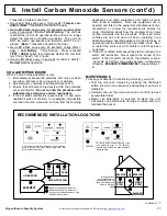
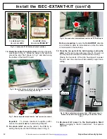
6.
On the back of the unit, re-
move the four (4) screws that
secure the rear housing and
pull off the rear housing (see
Fig. 1).
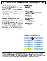
7.
Remove the two screws that
secure the
Wall Outlet PCB
(see Fig. 3). Unplug the
Wall Outlet PCB
and place
into the supplied anti
-
static
bag/sheet for possible future
use.
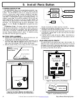
8.
On the inside rear housing,
insert the
Rubber Gasket
that covers the slots for the
Wall
Outlet PCB
prongs (see Fig. 4).
9.
Install batteries (observing polarity) and the unit powers up*.
10.
Replace the rear housing; secure with the four (4) screws.
11.
Secure unit to the wall by using a screw (appropriate for the
mounting surface) inserted into the
Screw Hole Tab
shown
on the templates.
12.
Install the
Finisher Plate
to conceal the
Tamper Magnet
(see Fig. 2).
Note:
In areas where power outages are common, we recommend
a 5 minute sounder cutoff to maximize battery life.
*Every time the siren is powered from an unpowered state, the unit ignores the tamper function until after the siren is placed over the tamper magnet. Subsequently, when the normally
-
closed tamper
circuit opens (magnet removed), the siren reports a tamper trouble to the Go
-
Anywhere Hub. In addition, pressing the keypad
RESET
button sends an updated status from the
ISEC
-
WL
-
SIREN
to the
Go
-
Anywhere Smart Hub.
Fig. 1: Rear of the unit
Fig. 2: Finisher Plate
Fig. 3: Remove the two "Wall
Outlet PCB" screws
Fig. 4: Rubber Gasket
ISEC-WL-SIREN
Wireless Siren


