


Napco iSecure Security System
All technical manuals are available in PDF format at
tech.napcosecurity.com
23
2.
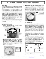
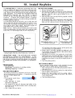
Locate the RF ID#
Locate the RF ID# on the rear of the unit.
NOTE:
The RF
ID# on the label must be accurately recorded in order to
map the transmitter into the system (see Step 7).
3.
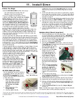
Install the battery
Observing polarity, install the supplied battery as shown.
NOTE:
A Tamper zone trouble will result when the batter-
ies are replaced.
Replace battery with a 3V Duracell
DL123A, Varta/Power
-
One CR123A or Panasonic CR123A
only. Use of another battery may present a risk of fire or
explosion
.
CAUTION:
Risk of Fire, explosion and burns. Do not re-
charge, disassemble, heat above 100°C., or incinerate.
Dispose of used batteries promptly. Keep away from chil-
dren.
4.
Mounting the base to the ceiling
Select mounting location for detector on ceiling; maximum
spacing (10ft ceiling) is 50
-
feet x 50
-
feet*. Do not lo-
cate in direct path of hot or
cold air flow. Mark holes
using the accompanying
mounting template. Use
the two screws and an-
chors provided to attach
the mounting plate to the
wall or ceiling.
DESCRIPTION
The ISEC
-
HEAT is a high
-
quality 135°F (57°C) fixed tem-
perature detector with Rate of Rise. It is compatible with
the NAPCO iSecure
-
series supervised security system.
Protected coverage area is 50' x 50' with a ten foot ceiling
height. The ISEC
-
HEAT incorporates circuitry that will
transmit an alarm signal upon an alarm condition, generate
an hourly supervisory test signal to the receiver and also
monitor and annunciate low battery.
Coding switches are not required or used in the ISEC
-
HEAT. Each transmitter is assigned a unique identification
code number at the factory. The transmitter is powered by
one 3V Lithium battery (supplied) which can power the unit
for up to two years. If the battery voltage drops below nor-
mal, a low
-
battery report will be sent to the receiver with
any status or alarm transmission. If a low
-
battery condition
is indicated, replace the
battery.
OPERATION
Rate
-
of
-
Rise Feature:
A temperature increase of 15°F or
more per minute will result in an alarm transmission. When
the rate
-
of
-
rise element alone has been activated, the de-
tector is self
-
restoring.
Fixed Temperature:
If the temperature of the center disk
rises to the detector
’
s rated temperature (135°F / 57°C) an
alarm transmission will result. When actuated by the fixed
temperature element, the detector is non
-
restorable and
must be replaced. The need for replacement is indicated
when the center disk has fallen free; order System Sensor
model 5601P to replace detector.
When the ISEC
-
HEAT detects an alarm as described
above, the integral transmitter sends an alarm signal to the
receiver. The alarm signal is repeated every 10 seconds
thereafter as long as the alarm condition is present. A re-
store report is sent when the condition clears.
1.
Remove the mounting base.
Lift the ISEC
-
HEAT from the base by turning the top of the
heat detector counter
-
clockwise while holding the base sta-
tionary.
7. Install Heat Sensors
WARNING: NOT A LIFE SAFETY DEVICE
-
USE FOR PROPERTY PROTECTION ONLY
continued
NOTE:
RF ID# is
located on the label
placed on the rear
of the unit
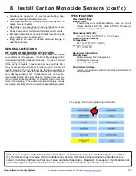
To AutoEnroll using
the ISEC
-
WL
-
TOUCH keypad,
see page 65.


