background image


User’s Guide DrafStation and Drafstation Pro

Chapter 3: Basics


 60 

AP-75730, Rev. 2.1, 19/01/2009 


Step 7 : 

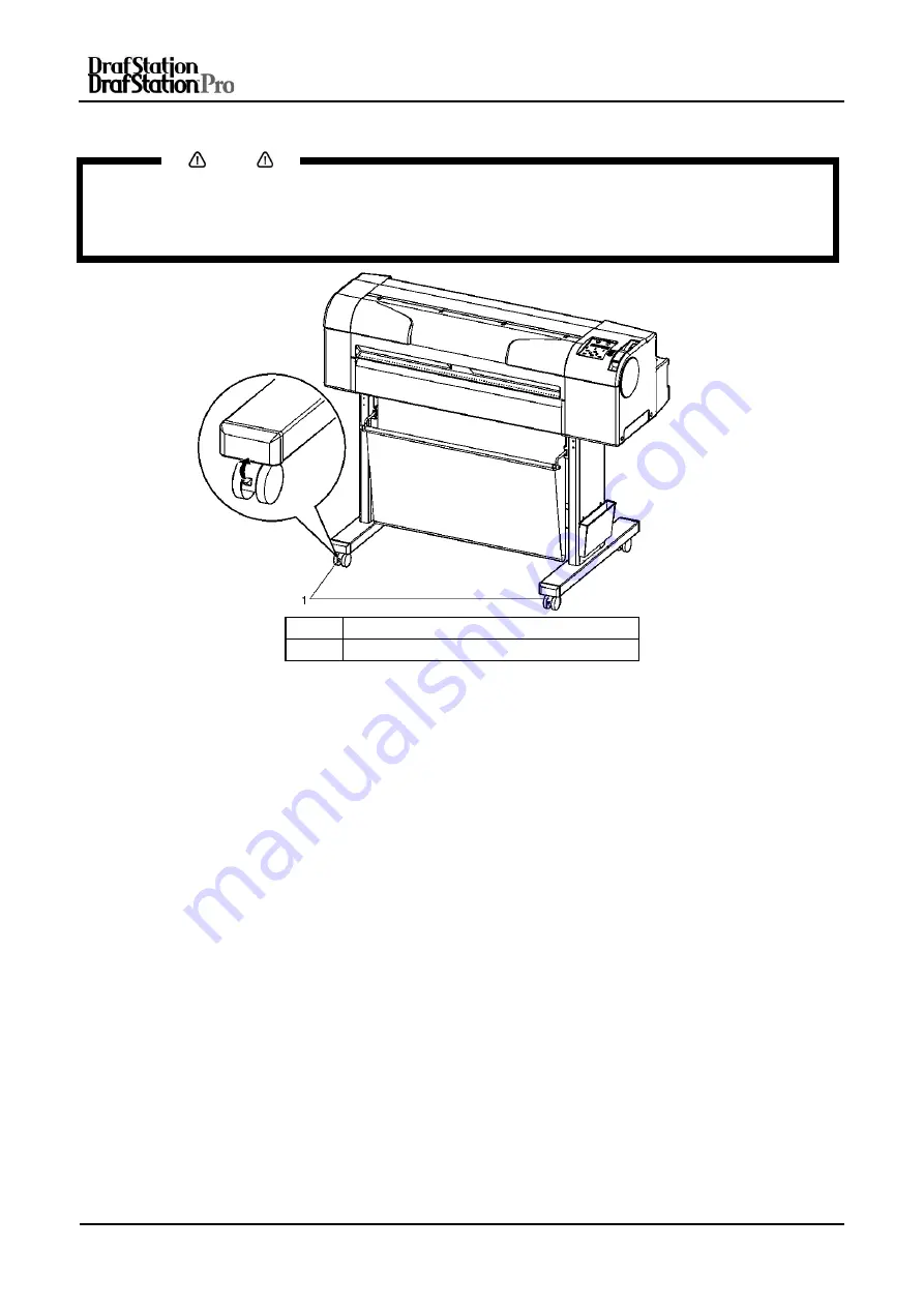
Release the lock of the caster and transfer the plotter. 


Notes


  The casters supplied with the dedicated stand are manufactured for a small transfer on a plain surface. 

When moving the plotter outdoors, and in places with big step differences, than move the stand and 
plotter separately.  

  Refer to the Installation guide. 


N° Name 

1 Caster 


(2) Steps after transfer 

 
After transfer, follow the steps below. 
 

Step 1 : 

Choose a suitable place for installation and place the plotter. 

See 

Installation guide 


Step 2 : 

Verify that the butterfly bolts fixing the stand with the plotter are not loosening. 


Step 3 : 

Connect all cables. 


Step 4 : 

Perform a nozzle check, and verify that there is no clogging in the plotter head.  

Refer to: NozzleCheck”


Step 5 : 

Perform a head alignment. 

Refer to: “AdjustPlot “ 


Summary of Contents for DrafStation

Page 1: ...User s Guide DrafStation Drafstation Pro FOR EUROPE ONLY ...

Page 2: ...User s Guide DrafStation and Drafstation Pro 2 AP 75730 Rev 2 1 19 01 2009 This page is intentionally left blank ...

Page 3: ...arty to whom it is given assumes its custody and control and agrees to the following The information herein contained is given in confidence and any part thereof shall not be copied or reproduced without written consent of Mutoh Europe N V This document or the contents herein under no circumstances shall be used in the manufacture or reproduction of the article shown and the delivery of this docum...

Page 4: ...V shall not be liable for any damages or troubles resulting from the use of this equipment or this guide ABOUT THIS GUIDE Purpose and Target Readers Thank you for purchasing this plotting product We are so grateful to you This guide explains preparations before use and operation procedures for MUTOH s Full Colour Inkjet plotter RJ 900 901C series This guide is prepared for the owners and operators...

Page 5: ... 901C 22 2 2 5 Rear section Drafstation RJ 900C and Drafstation Pro 23 2 2 6 Operation panel 24 2 3 IN THE BOX CONTENTS DRAFSTATION RJ 900 RJ 901 27 2 3 1 Items in the plotter box 27 2 3 2 Items in the Starter kit 27 2 3 3 Items in the stand box 28 2 4 IN THE BOX CONTENTS DRAFSTATION PRO 29 2 4 1 items in the plotter Box 29 2 4 2 Items in the Starter kit 29 2 4 3 Items in the stand box 30 2 4 4 It...

Page 6: ...ng the Windows plotter driver for USB connection 70 3 10 5 Installing the status monitor 86 3 10 6 Uninstalling the software 89 4 PERIODICAL MAINTENANCE 91 4 1 DONE BY THE END USER 92 4 1 1 Cleaning the plotter 92 4 1 2 Cleaning the outer case 92 4 1 3 Cleaning inside the plotter 93 4 1 4 Head cleaning 94 5 PREPARATIONS BEFORE PRINTING 95 5 1 GENERAL INFO ON USABLE MEDIA 96 5 1 1 Media compatibili...

Page 7: ...int mode 126 7 TROUBLESHOOTING 127 7 1 MALFUNCTION AND FAILURE OF THE PRODUCT 128 7 1 1 Problem at installation and introduction 128 7 1 2 Cannot generate graphics 129 7 1 3 Media related troubleshooting 130 7 1 4 Printing related troubleshooting 133 7 2 ERROR MESSAGES 134 7 2 1 Status messages 134 7 2 2 Error message display and remedies 135 7 2 3 Data error display and remedies 136 7 2 4 Command...

Page 8: ...User s Guide DrafStation and Drafstation Pro 8 AP 75730 Rev 2 1 19 01 2009 This page is intentionally left blank ...

Page 9: ...PLY WITH FOLLOWING REGULATIONS 10 1 2 WARNINGS CAUTIONS AND NOTES 10 1 3 IMPORTANT SAFETY INSTRUCTIONS 11 1 4 WARNING LABELS 13 1 4 1 Handling the operation procedure labels 13 1 4 2 Locations and types of warning labels 13 1 5 OPERATION PROCEDURE LABELS 15 1 5 1 Handling the operation procedure labels 15 1 5 2 Locations and types of warning labels 15 ...

Page 10: ...ched to a product it means the product is covered by the European Directive 2002 96 EC WEEE regulation Please inform yourself about the local separate collection system for electrical and electronic products Please act according to your local rules and do not dispose of your old products with your normal household waste The correct disposal of your old product will help prevent potential negative ...

Page 11: ...tric shock and fire Immediately switch off the power switch disconnect the power plug from the electric socket and contact your local MUTOH dealer While installing optional items be sure to switch OFF the power of the plotter and pull out the power plug It could lead to an electric shock Wire the various codes cable as explained in the User s Guide Wrong wiring could cause fire Be sure to use the ...

Page 12: ...ver normal operation after shifting to these positions cannot be guaranteed Opening and moving the plotter to the installation place must be done by o RJ 901C 2 or more persons o RJ 900C Drafstation Pro 3 or more persons While taking out the plotter from the container box make sure to remove the vinyl sheet and hold the handles on the plotter side If the plotter is lifted with the vinyl sheet atta...

Page 13: ...n procedure labels When handling the warning labels be careful about the following points Notes Check whether all the warning labels are readable If the letters or illustrations on the label are not clear remove the dirt from the label Use cloth water and neutral detergent for removing dirt from the warning label Avoid either organic solvents or gasoline It is necessary to replace the labels if th...

Page 14: ...User s Guide DrafStation and Drafstation Pro Chapter 1 Safety information 14 AP 75730 Rev 2 1 19 01 2009 N Types of warning label 1 2 3 4 5 6 ...

Page 15: ...procedure labels Notes Check whether all operation procedure labels are readable If the letters or illustrations on the labels are not clear remove the dirt from the label Use cloth water and neutral detergent for removing dirt from an operation procedure label Avoid using either organic solvents or gasoline It is necessary to replace the labels if they are damaged lost or illegible If the operati...

Page 16: ...User s Guide DrafStation and Drafstation Pro Chapter 1 Safety information 16 AP 75730 Rev 2 1 19 01 2009 This page is intentionally left blank ...

Page 17: ...2 2 2 5 Rear section Drafstation RJ 900C and Drafstation Pro 23 2 2 6 Operation panel 24 2 3 IN THE BOX CONTENTS DRAFSTATION RJ 900 RJ 901 27 2 3 1 Items in the plotter box 27 2 3 2 Items in the Starter kit 27 2 3 3 Items in the stand box 28 2 4 IN THE BOX CONTENTS DRAFSTATION PRO 29 2 4 1 items in the plotter Box 29 2 4 2 Items in the Starter kit 29 2 4 3 Items in the stand box 30 2 4 4 Items in ...

Page 18: ...e drawings to CAD images 2 Ink system The ink cartridges and the ink system are designed to avoid soiling your hands during ink replacement Black pigment ink is employed which is abundantly used in line drawings offering high printing quality on different media and an improved weather resistance 3 Ultimate working efficiency This plotter is designed for handling roll media RJ 901C only and sheet m...

Page 19: ...section Drafstation RJ 901C N Name Function 1 Media hold lever To fix and release media 2 Operation panel To set the operation conditions and various function settings 3 Front cover To protect the user from coming in contact with the driving mechanism during operation 4 Waste fluid tank To collect the plotter s waste ink Optional parts N Name Function 5 Stand To install the plotter on a levelled f...

Page 20: ...d release media 2 Operation panel To set the operation conditions and various function settings 3 Front cover To protect the user from coming in contact with the driving mechanism during operation 4 Waste fluid tank To collect the plotter s waste ink 5 Stand To install the plotter on a levelled floor 6 Paper basket To hold the finished plots 7 Book holder To store plotter documentation ...

Page 21: ...er To fix and release media 2 Operation panel To set the operation conditions and various function settings 3 Front cover To protect the user from coming in contact with the driving mechanism during operation 4 Waste fluid tank To collect the plotter s waste ink 5 Stand To install the plotter on a levelled floor 6 Take Up system To Roll up the finished plots 3 2 1 4 5 6 ...

Page 22: ...tation RJ 901C N Name Function 1 AC inlet To connect the power cable 2 Network interface connector To connect the network interface cable 3 USB connector To connect the USB cable 4 Scroller receiver To install the scroller with roll media 5 Media feed slot To insert roll media 6 Ink cartridge slots To install the ink cartridges ...

Page 23: ...900C and Drafstation Pro N Name Function 1 AC inlet To connect the power cable 2 Network interface connector To connect the network interface cable 3 USB connector To connect the USB cable 4 Scroller receiver To install the scroller with roll media 5 Media feed slot To insert roll media 6 Ink cartridge slots To install the ink cartridges ...

Page 24: ...f each operation key and status light The operation keys have 2 different functions depending on the plotter mode Mode Key functions Normal mode Various functions for printing can be performed on the operation panel Menu mode Various setup items e g IP address HPGL settings pen setup etc can be set on the operation panel For details on the plotter mode refer to Plotter mode ...

Page 25: ... colour Black White light up green 6 Backward feed Feeds the media in reverse direction Setting value 7 Forward feed Feeds the media in forward direction Setting value 8 Power Switches the plotter ON OFF 2 Operation keys in the Menu mode N Key Function 1 Menu Shifts from Menu mode to Normal mode 2 Enter Selects a specific menu or submenu To enter and save the value Cleaning 3 Cancel Returns to the...

Page 26: ...de is set to Colour Light OFF Colour mode is set to Black White 14 Black white light Green Light ON Colour mode is set to Black White Light OFF Colour mode is set to Colour 15 High speed Green Light ON The print mode is set to high speed When Normal light is also on the print mode is set to high quality Light OFF The print mode is set to normal 16 Normal Green Light ON The print mode is set to nor...

Page 27: ... damaged or missing contact your local MUTOH dealer 2 3 1 Items in the plotter box 1 RJ 901C N Name Quantity 1 Plotter body 1 2 A1 Scroller 2 inch 1 2 RJ 900C N Name Quantity 1 Plotter body 1 2 A0 Scroller 2 inch 1 2 3 2 Items in the Starter kit N Name Quantity 1 Power Cable Europe 1 2 Power Cable UK 1 3 USB cable 1 4 User s Guide 1 5 Installation CD and drivers 1 6 CD with Mutoh manuals 1 7 Ink s...

Page 28: ... 2 1 19 01 2009 2 3 3 Items in the stand box N Name Quantity 1 Left support 1 2 Right support 1 3 Caster section left right 2 4 Central beam 1 5 Basket support holder 2 6 Basket support 2 7 Book holder 1 8 Paper basket 1 9 Hexagon head cap screw 8 10 Butterfly bolt 2 11 Hexagonal wrench 1 ...

Page 29: ... 1 Plotter body 1 2 A0 Scroller 2 inch 1 2 4 2 Items in the Starter kit N Name Quantity 1 Power Cable Europe 1 2 Power Cable UK 1 3 USB cable 1 4 User s Guide 1 5 Installation CD and drivers 1 6 CD with Mutoh manuals 1 7 Ink starter set 4 cassettes 1 8 Flange spacer 3 inch 2 Notes Depending on your choice you will have an ink starter set with 110ml cassettes or a set with 220ml cassettes ...

Page 30: ...t 2 4 Central beam 1 5 Hexagon head cap screw 8 6 Butterfly bolt 2 7 Book holder 1 8 Hexagonal wrench 1 2 4 4 Items in the Take up system box N Name Quantity 1 Left bracket 1 2 Right bracket with drive mechanism 1 3 Sensor bracket 1 4 Sensor cable 1 5 Scroller bar with 2 3 flanges 1 6 Power cable EU 1 7 Power cable US 1 8 Hexagon ball wrench 1 9 User s Guide Take up 1 10 Cable guide 3 11 Locking c...

Page 31: ...2 5 1 Environmental conditions for installation Floor strength of installation place More than 2940 Pa 300 kg m Power Specifications Power Supply AC90V 132V 198V 264V Frequency Range 50 60Hz 1Hz Power Capacity More than 10 A Environmental conditions Operative Condition Temperature 10 C to 35 C Humidity 20 to 80 no condensation Guaranteed range of printing accuracy Temperature 15 C to 28 C Humidity...

Page 32: ... which has enough strength to support the weight of the plotter and the stand 2 When using the plotter only RJ 901C only Install the plotter on a levelled table which has fulfils the following conditions The table is strong enough to support the weight of the plotter The required length for the sheet media is available at the back of the machine The height from the floor is 600 mm to 800 mm The sp...

Page 33: ...r setup items 47 3 5 REPLACING ROLL MEDIA 48 3 6 REPLACING INK CARTRIDGES 51 3 6 1 Cartridge types for Drafstation 51 3 6 2 Cartridge types for Drafstation Pro 51 3 7 REPLACING THE CUTTER BLADE 54 3 8 REPLACING THE WASTE FLUID TANK 57 3 9 TRANSFER AND TRANSPORTATION 59 3 9 1 Transferring the plotter 59 3 9 2 Transporting the plotter 61 3 10 INSTALLING AND UNINSTALLING THE SOFTWARE 62 3 10 1 Conten...

Page 34: ...initial start up operations the unit will enter the normal operation condition 3 1 2 Switching the power OFF Power OFF the printer according to the procedure below Step 1 Verify the following operational conditions of the unit The printer is not performing any printing operation The operation panel is in the main screen Step 2 Press the OFF key on the operation panel to power OFF the printer Step ...

Page 35: ...900C and Drafstation Pro three inches diameter media core outer diameter less than 150 mm weight less than 19 kg When using the three inch core adapter on the scroller the following roll media can be loaded o RJ 901C three inches diameter media core outer diameter less than 100 mm o RJ 900C and Drafstation Pro three inches diameter media core outer diameter less than 150 mm For details refer to th...

Page 36: ...f using media on a 2 inch core Don t use the three inch core adapters go to step 3 If using media on a 3 inch core Click a three inch core adapter 3 on the fixed flange 2 and the movable flange 1 as shown on the image below N Name 1 Movable flange 2 Fixed flange 3 Three inch core adapter Step 3 Put the roll media on the scroller See image below for the correct roll direction Printable side outside...

Page 37: ... flange 2 Roll media Step 5 Move the movable flange 1 over the scroller and firmly press the flange inside the roll media core See image below 1 Movable flange 2 Roll media Step 6 Put the scroller 1 on the plotter s scroller receiver 4 so that the fixed flange 2 is facing the ink cartridge slot side See image below N Name 1 Scroller 2 Fixed flange 3 Ink cartridge slot 4 Scroller receiver ...

Page 38: ...using the Drafstation Pro a Take up system can be used For installing and using the Take up system refer to the user s guide of the Take up system To load the roll media follow the steps below Step 1 Switch ON the plotter Result o The plotter initializes o The operation panel displays Paper End Step 2 Press the Back key on the operation panel and select Roll Result The Roll media light lights up N...

Page 39: ...core If the front edge of the roll media is not straight cut it straight using the cutter blade If the front edge of the roll media is curled cut it off using the cutter blade For the cutting method refer to topic Cutting media Step 5 Open the front cover 1 and pull out the roll media 2 about 0 5 m N Name 1 Front cover 2 Roll media Step 6 Verify that the right edge of the roll media does not cover...

Page 40: ...nd avoid slant of the media See images below N Name 1 Roll media 2 Scroller Step 8 Pull the media hold lever 1 forward as shown on the image below N Name 1 Media hold lever Notes If the front edge of the roll media is not straight cut it straight For the cutting method Refer to Cutting media If the length of the edge to be cut is set on the media setup menu the roll media edge will be automaticall...

Page 41: ...otes When roll media is loaded wind back the roll media before loading sheet media When using the paper basket refer to Paper basket setting the paper basket cannot be used if the Take up system is mounted To load sheet media follow the steps below Step 1 Switch ON the plotter Result The plotter initialises The operation panel displays Paper End Step 2 Press the Back key of operation panel and sel...

Page 42: ...edia feed slot at the front side of the plotter See image below N Name 1 Sheet media Step 6 Align the right hand side of the sheet to the media loading mark 2 and align the front edge to one of the platen steps 3 See image below N Name 1 Sheet media 2 Media loading mark 3 Platen step Notes Load the media within a 5mm range left or right from the loading mark otherwise a media loading error will oc...

Page 43: ...3 Basics 43 AP 75730 Rev 2 1 19 01 2009 Step 7 Pull the media hold lever 1 forward See image below N Name 1 Media hold lever Step 8 Close the front cover 1 See image below N Name 1 Front cover Result The operation panel displays the Media type setup menu ...

Page 44: ...ype when o Pressing the Cancel key o No key operations are performed on the operation panel for 10 seconds Procedure Step 1 Verify that the printer has been switched ON and the media has been loaded Result The display shifts to the media setup menu after loading media Step 2 Press the Setting value key or Setting value key on the operation panel to select the correct media type User1 User2 User3 U...

Page 45: ...ved media Notes If raising the head height adjustment lever high print quality will not be guaranteed Do not open the front cover nor change the head height during printing If changing the head height the head alignment will be changed and high print quality will not be guaranteed Procedure Step 1 Open the front cover Step 2 Move the head height adjustment lever to change the head height See image...

Page 46: ...ints preventing them from spotting or folding Notes The paper basket cannot be mounted when you are using a Drafstation Pro with take up system Action Pull out the tray hook as far as possible N Name 1 Tray hook Notes To set the Take up system for the Drafstation Pro refer to the User s Guide of the Take up system This section describes how to make the fully installed plotter ready to print For de...

Page 47: ...river setup screen Read the instructions to set the plotter settings 3 4 2 Plotter driver setup items This section describes the plotter driver setup items Setup item Description Basic setup To set up the basic setup items of printing and to check the setup list Advanced setup To set up the advanced settings of the printing conditions and to check the setup list Options To perform the setup items ...

Page 48: ...lace roll media if the roll media runs out The operation panel displays End of Roll If the media runs out during printing the plotter stops printing you want to change the media type 2 Type Notes For types and details of roll media refer to Options Supplies 3 Replacement steps To replace roll media follow the procedure below Note that the procedure consists of 2 parts 1 Remove the installed roll m...

Page 49: ...ow N Name 1 Roll media 2 Scroller Step 4 Remove the scroller 1 from the scroller receiver as illustrated below and place it on a horizontal surface N Name 1 Scroller Step 5 Hold the movable flange 1 and tap the scroller 2 as illustrated below to remove the movable flange N Name 1 Movable flange 2 Scroller Notes When removing roll media do not drop it Doing so will damage the scroller ...

Page 50: ...Name 1 Roll media 2 Scroller 2 Install the new roll media Notes For loading the roll media refer to Handling and installing Media For storing media store it according to Notes on storing media Notes When you do not load roll media then attach the movable flange to the scroller and set the scroller on the plotter See image below N Name 1 Movable flange 2 Scroller ...

Page 51: ... the new ink cartridge has been inserted If there is no new ink cartridge for replacement then leave the empty ink cartridge into the plotter Leaving the plotter without ink cartridges inside the ink cartridge slots may result in head clogging 3 6 1 Cartridge types for Drafstation Description Part N Ink cartridge K Black 110 ml RJ9 INK BK Ink cartridge C Cyan 110 ml RJ9 INK C Ink cartridge M Magen...

Page 52: ...lurred and the end of ink in the cartridge might no longer be correctly detected o The problems caused by doing so will not be covered by the warranty and repair expenses will have to be paid by the customer For types and details of ink cartridges refer to Options Supplies When moving an ink cartridge from a cold place to a warm place keep the ink cartridge unused for three hours or more in the pr...

Page 53: ... N Name 1 Empty ink cartridge 2 Ink cartridge slot Step 3 Unpack the new ink cartridge s Notes When replacing ink cassettes on the Drafstation Pro be aware to insert the same ink cassettes as those who were in previous If you insert the second configuration without performing a cleaning the printer will be defected When you want to switch from 1 configuration to another contact your local Mutoh de...

Page 54: ... the genuine cutter blade Description Model N Substitute cutter blade RJ3 CBS 3 Replacement steps To replace the cutter blade follow the steps below Step 1 Verify that the plotter is ON Step 2 Press the Menu key on the operation panel to display the setup menu Notes For key operations on the setup menu refer to Menu setup on the operation panel Step 3 Go to the CutterChange menu Step 4 Select Cutt...

Page 55: ...y release the cutter holder knob to prevent the built in spring from springing out Do not push the cutter holder to the end The cutter blade will damage the inside of the plotter Step 7 Remove the cutter as shown on the image below N Name 1 Cutter Notes The used cutter must be put in a vinyl bag or bag used for this kind of waste Disposal of a cutter blade has to be done in compliance with the reg...

Page 56: ... Notes Do not strongly press or suddenly release the cutter holder knob to prevent the built in spring from springing out o Do not push the cutter holder to the end The cutter blade will damage the inside of the plotter o Correctly install the cutter holder lever referring to the image shown in this step of the procedure Incorrect installation will generate errors If an error occurs check that the...

Page 57: ...nkTank is displayed on the operation panel The waste fluid tank is full Printing stops Action Immediately replace the waste fluid tank 2 Type See below for the waste fluid tank that can be used on this plotter Description Model N Waste fluid tank DE 36686 3 Replacement steps To replace the waste fluid tank follow the 5 steps below Step 1 Verify that the plotter has been switched ON Step 2 Pull out...

Page 58: ...e plotter as shown on the image below N Name 1 Waste fluid tank Step 4 Verify that the operation panel displays Exchange Tank No Step 5 Select Yes and press the Enter key on the operation panel Notes In case of pulling out the waste fluid tank accidentally press the Enter key on the operation panel when Exchange Tank No is being displayed ...

Page 59: ...the dedicated stand transfer the plotter following the procedure below 1 Pre transfer steps Step 1 Verify that the plotter has been switched OFF Step 2 Verify that the butterfly bolts attaching the stand with the plotter are not loosen Step 3 Verify that the plotter head is in the rightmost position Step 4 Attach the protective material metal plate for attaching the head unit 1 and fix it with thu...

Page 60: ...ferences than move the stand and plotter separately Refer to the Installation guide N Name 1 Caster 2 Steps after transfer After transfer follow the steps below Step 1 Choose a suitable place for installation and place the plotter See Installation guide Step 2 Verify that the butterfly bolts fixing the stand with the plotter are not loosening Step 3 Connect all cables Step 4 Perform a nozzle check...

Page 61: ...the plotter Result The operation panel displays Transport Mode and the plotter starts the ink rejecting operation The ink rejecting operation takes about 2 minutes Step 5 Verify that the power light faints when the ink rejection operations has been finished Step 6 Remove the scroller Step 7 Remove all cables Step 8 Attach the protective material metal plate for attaching the head unit 1 and fix it...

Page 62: ...000 XP The plotter driver installation procedure depends on how the plotter will be connected to your PC Perform installation as shown in the following procedure For network connection Refer to Installing the plotter driver for network connection For USB connection Refer to Installing the plotter driver for USB connection Notes Refer to the following files contained on the CD ROM for the latest in...

Page 63: ...Name Function 1 Plotter type Plotter for which the operating state has to be checked is selected 2 Residual ink quantity Displays residual ink quantity of K C M and Y 3 Media information Displays Media type residual quantity etc 4 Plotter information Displays the operating status of the plotter 5 Monitor start button Starts monitoring the Drafstation 6 Quit button Closes the Status monitor softwar...

Page 64: ... _2006 02 16_MEN Example of the Windows plotter software folder 14 06 2006 16 56 DIR 14 06 2006 16 56 DIR 15 12 2005 18 00 27 Autorun inf 15 02 2006 01 56 8 331 DriverInfo INI 15 12 2005 18 00 12 850 Readme txt 14 06 2006 16 47 DIR RJ 900C_2000_XP 14 06 2006 16 47 DIR RJ 900C_95 14 06 2006 16 47 DIR RJ 900C_NT40 14 06 2006 16 47 DIR RJ 900_PROGRAM 14 06 2006 16 47 DIR RJ 900_PROGRAM 95 14 06 2006 ...

Page 65: ...s to this IP address Subnet mask plotter Has to be filled out in the plotter Gateway plotter This is the PC s IP address or the router s IP address on the plotter side Has to filled out on the plotter Notes When installing a router between the plotter and the PC IP forwarding of the plotter s IP address to the PC is necessary This to establish bidirectional communication between the plotter and th...

Page 66: ...re switched ON 2 Insert the driver CD in the CD drive of the PC OR run the setup exe file in the Windows plotter software folder Notes When the Installer does not automatically start execute Setup exe on the CD ROM The software initializes The display moves to screen 1 of the Mutoh printer driver program 3 Select the model in screen 1 and click Install Screen 1 The display moves to screen 2 4 Clic...

Page 67: ...Result 5 Click Agree or Cancel in screen 3 License agreement of the plotter driver a When you agree to the license agreement Click Agree The display moves to Screen 4 b When you do not agree to the license agreement Click Cancel Screen 3 The display moves to screen 4 when you agree with the conditions 6 Click Network in Screen 4 Screen 4 The display moves to screen 5 ...

Page 68: ...printer port OR Screen 5a The display moves to screen 6 in Step 8 Select a port click OK and go to step 9 to select an existing port Notes The RJ 90x Port is displayed if a port setup has been performed already in the past Select the port and click configure port to use it Screen 5b The display moves to Screen 7 in step 9 8 Select Mutoh Network Port and click New Port Screen 6 The display moves to...

Page 69: ...the Setting button See below for settings Port name Fill out the port name Eg RJ901 any name is possible IP Address Fill out the plotter s IP address as chosen in step 2 Screen 7 The display moves to Screen 8 10 Check the contents on the display and click Next Screen 8 Installation of the driver is started The display will show a progress bar and moves to screen 9 11 Click End in screen 9 Screen 9...

Page 70: ...ty warnings before handling the printer The procedure to install the plotter using the USB connection consists of 2 parts and a third optional part Part 2 and Part 3 are separately presented for Windows XP and Windows 2000 Follow the procedure in the following order Part 1 Mutoh installer Part 2 Win XP PnP mode Part 2 Win 2000 PnP mode Part 3 Win XP Guide mode OPTIONAL Use only when PnP has failed...

Page 71: ... Insert the driver CD in the CD drive of the PC OR run the setup exe file in the Windows plotter software folder Notes When the Installer does not automatically start execute Setup exe on the CD ROM The software initializes The display moves to screen 1 of the Mutoh printer driver program 3 Select the plotter model in screen 1 and click Install Screen 1 The display moves to screen 2 4 Click the ch...

Page 72: ...plotter driver a When you agree to the license agreement Click Agree The display moves to Screen 4 b When you do not agree to the license agreement Click Cancel Screen 3 The display moves to screen 4 when you agree with the conditions 6 Click USB in Screen 4 Screen 4 The display moves to screen 5 7 Check the contents on the display and click Next Screen 5 Installation of the driver has started The...

Page 73: ...ro Chapter 3 Basics 73 AP 75730 Rev 2 1 19 01 2009 Win USB installation procedure Part 1 Mutoh installer 8 steps Step 8 Step Action Screen Result 8 Click End and Go to Part 2 of the USB installation Screen 6 End of Part 1 the installer finishes ...

Page 74: ...river CD is inserted in the CD ROM drive of the PC and the Mutoh installer Part 1 has been finalized 2 Connect the plotter to the PC with the USB cable The display moves to screen 1 of the Found New Hardware Wizard 3 Mark the checkbox No not this time in screen 1 and click on Next Screen 1 The display moves to screen 2 4 Mark the checkbox Install from a list or specific location Advanced in screen...

Page 75: ...ure Part 2 WinXP PnP mode 12 steps Step 5 to 7 Step Action Screen Result 5 Mark the checkbox Don t search I will choose the driver to install in screen 3 and click on Next Screen 3 The display moves to screen 4 6 Click Have Disk Screen 4 The display moves to screen 5 7 Click Browse Screen 5 The display moves to screen 6 ...

Page 76: ...on Screen Result 8 Browse to the file RJ901C inf or RJ900C inf on the Mutoh Driver CD or the Windows plotter software folder Select the file Click Open Notes RJ 901C RJ901C inf RJ 900C RJ900C inf Screen 6 The display moves to screen 7 9 Click OK in screen 7 Screen 7 The display moves to screen 8 10 Choose the Mutoh printer and click Next Screen 8 The display moves to screen 9 ...

Page 77: ...30 Rev 2 1 19 01 2009 Win USB installation procedure Part 2 WinXP PnP mode 12 steps Step 11 to 12 Step Action Screen Result 11 Click Continue Anyway in screen 9 Screen 9 The display moves to screen 10 12 Click Finish in Screen 10 Screen 10 The plotter is now installed END ...

Page 78: ...is inserted in the CD ROM Drive of the PC and The Mutoh installer has finished 2 Connect the plotter to the PC with the USB cable See Error Reference source not found Error Reference source not found The display moves to screen 1 of the Found New Hardware Wizard 3 Click Next in screen 1 Screen 1 The display moves to screen 2 4 Mark the checkbox Search for a suitable driver for my device Recommende...

Page 79: ...on procedure Part 2 Win2000 PnP mode 8 steps Step 5 to 7 Step Action Screen Result 5 Mark the checkbox CD ROM drives in screen 3 and click on Next Screen 3 The display moves to screen 4 6 Click Next in screen 4 Screen 4 The display moves to screen 5 7 Click Yes in screen 5 Screen 5 The display moves to screen 6 ...

Page 80: ... Drafstation Pro Chapter 3 Basics 80 AP 75730 Rev 2 1 19 01 2009 Win USB installation procedure Part 2 Win2000 PnP mode 8 steps Step 8 Step Action Screen Result 8 Click Finish in screen 6 Screen 6 The plotter is now installed END ...

Page 81: ... steps Step 1 to 3 Step Action Screen Result 1 Go to Control Panel Printers and click Add Printer The display moves to screen 1 of the Add Printer wizard 2 Click Next in screen 1 Screen 1 The display moves to screen 2 3 Mark Local printer UN mark Automatically detect and install my Plug and Play printer Click Next Screen 2 The display moves to screen 3 ...

Page 82: ...teps Step 4 to 6 Step Action Screen Result 4 Select the USB printer port Virtual printer port for Mutoh in screen 3 and click Next Screen 3 The display moves to screen 4 5 Select Mutoh Industries Ltd in screen 4 and click the Have Disk button Screen 4 The display moves to screen 5 6 Click the Browse button screen 5 Screen 5 The display moves to screen 6 ...

Page 83: ... Result 7 Browse to the file RJ901C inf or RJ900C inf on the Mutoh driver CD or the Window plotter software folder Select the file Click Open Notes RJ 901C RJ901C inf RJ 900C RJ900C inf Screen 6 The display moves to screen 7 8 Click OK in screen 7 Screen 7 The display moves to screen 8 9 Click on MUTOH RJ 900C or MUTOH 901C in screen 8 and click Next Screen 8 The display moves to screen 9 ...

Page 84: ...0 to 12 Step Action Screen Result 10 Select Replace existing driver in screen 9 and click Next Screen 9 The display moves to screen 10 11 Fill out the printer name in screen 10 and click Next Notes Any name is possible E g MUTOH RJ 901C Screen 10 The display moves to screen 11 12 Choose to share the printer or not and click Next Screen 11 The display moves to screen 12 ...

Page 85: ...9 01 2009 Windows USB installation procedure Part 3 Win2000 Guide mode 14 steps Step 13 to 14 Step Action Screen Result 13 Choose to print a test page or not and click Next Screen 12 The display moves to screen 13 14 Click Finish in screen 13 Screen 13 The plotter is now installed END ...

Page 86: ...ocedure 7 steps Step 1 to 4 Step Action Screen Result 1 Verify that the PC and the plotter are switched ON 2 Insert the driver CD in the CD drive of the PC OR run the setup exe file in the Windows plotter software folder Notes When the Installer does not automatically start execute Setup exe on the CD ROM The software initializes The display moves to screen 1 of the Mutoh printer driver program 3 ...

Page 87: ...display moves to screen 3 5 Click Agree or Cancel in screen 3 License agreement of the plotter driver a When you agree to the license agreement Click Agree The display moves to Screen 4 b When you do not agree to the license agreement Click Cancel Screen 3 The display moves to screen 4 when you agree with the conditions 6 Check the contents on the display and click Next Screen 4 Installation of th...

Page 88: ...on Pro Chapter 3 Basics 88 AP 75730 Rev 2 1 19 01 2009 Windows Status monitor installation procedure 7 steps Step 7 Step Action Screen Result 7 Click End in screen 5 Screen 5 Installation is finalized The status monitor is now installed END ...

Page 89: ...otes If uninstalling the software the plotter driver AND status monitor are deleted Windows Uninstall procedure 4 steps Step 1 to 2 Step Action Screen Result 1 Insert the driver CD in the CD drive of the PC OR run the setup exe file in the Windows plotter software folder Notes When the Installer does not automatically start execute Setup exe on the CD ROM The software initializes The display moves...

Page 90: ...install procedure 4 steps Step 3 to 4 Step Action Screen Result 3 Click Next in Screen 2 Screen 2 The uninstallation of the software starts The display will show a progress bar and moves to screen 3 4 Click End in Screen 3 Screen 3 Uninstallation of the plotter drivers AND status monitor is completed END ...

Page 91: ...Pro Chapter 4 Periodical maintenance 91 AP 75730 Rev 2 1 19 01 2009 4 PERIODICAL MAINTENANCE 4 1 DONE BY THE END USER 92 4 1 1 Cleaning the plotter 92 4 1 2 Cleaning the outer case 92 4 1 3 Cleaning inside the plotter 93 4 1 4 Head cleaning 94 ...

Page 92: ... 1 DONE BY THE END USER 4 1 1 Cleaning the plotter Periodic every month cleaning is necessary to keep the plotter in a good condition This section describes how to clean each part of the plotter 4 1 2 Cleaning the outer case Instruction Use a soft cloth to wipe off the dust and possible dirt from the outer case ...

Page 93: ...Open the front cover 1 N Name 1 Front cover Step 2 Remove paper powder and dust from the pressure rollers 1 using a soft brush N Name 1 Pressure rollers Notes Do not blow paper powder inside the plotter Doing so will cause abnormal noise inside the plotter Step 3 Wipe off paper powder and ink from the printing board 1 using a dust free and soft cloth slightly damped with water N Name 1 Printing bo...

Page 94: ...Remove media while cleaning Step 1 Verify that the operation panel is in Normal mode Step 2 Verify that the media hold lever is positioned to the front side Step 3 Press the Cleaning key on the operation panel for at least 2 seconds See below Result The operation panel displays Cleaning minutes Step 4 Start the head cleaning Notes Pressing the Cleaning key again within one printing after the 1st h...

Page 95: ...ABLE MEDIA 96 5 1 1 Media compatibility 96 5 1 2 Printing area 98 5 1 3 Notes on handling media 99 5 1 4 Notes on storing media 99 5 2 TESTPLOT 100 5 2 1 Performing a testplot 100 5 2 2 SetupPlot 101 5 2 3 NozzleCheck 102 5 2 4 AdjustPlot 103 5 2 5 PalettePlot 104 5 2 6 MaintenanceRecordPlot 105 5 3 MEDIA FEED COMPENSATION 106 5 4 EFFECT MENU 110 5 5 PRINTING FLOW 111 ...

Page 96: ...es Lines Lines PlotReso dpi HS360 360 720 Direction BiDir BiDir UniDir ThinOut Black 100 100 70 InkDryTimer 30s 30s 60s Stiffness Soft Soft Soft 2 Col Trac Setup item High speed colour High speed black white Normal colour Normal black white High quality Colour High quality black white Condition Lines Lines Lines Lines Lines Lines PlotReso dpi 360 360 720 720 1440 1440 Direction BiDir BiDir BiDir B...

Page 97: ...ormal Normal Normal Normal 6 Photo Setup item High speed colour High speed black white Normal colour Normal black white High quality Colour High quality black white Condition Photo Lines Photo Lines Photo Lines PlotReso dpi 720 720 1440 1440 2880 Position specified 2880 Position specified Direction BiDir BiDir BiDir BiDir BiDir BiDir ThinOut Black 85 85 75 75 90 90 ThinOut Colour 55 60 50 InkDryTi...

Page 98: ...fStation and Drafstation Pro Chapter 5 Preparations before printing 98 AP 75730 Rev 2 1 19 01 2009 5 1 2 Printing area The printable area of the Drafstation and Drafstation Pro is as follows 1 Roll media 2 Sheet media ...

Page 99: ...limatized to the printing environment might cause media jams and bad print quality caused by media expansion or contraction Media has a printable side and a non printable side Printing on the non print side can cause blurs and blots Always handle media with dry and clean hands to avoid bad print quality When the plotter will be unused for more than 24 hours then remove the media to prevent media f...

Page 100: ...y that the plotter has been switched ON and that media roll or sheet more than A3 size has been loaded Refer to Loading roll media and Loading sheet media Step 2 Verify that the plotter is in Normal mode Step 3 Press the Menu key on the operation panel Result Displays the first submenu of the Setup menu The operation panel displays Menu TestPlot The plotter is in Menu mode Step 4 Press the Enter k...

Page 101: ...ation and Drafstation Pro Chapter 5 Preparations before printing 101 AP 75730 Rev 2 1 19 01 2009 5 2 2 SetupPlot To check the current settings of the plotter Notes For the printing procedure refer to Performing a testplot ...

Page 102: ...rnings before handling the printer Used to check whether there is any head clogging missing nozzles or misfiring nozzles Notes If the nozzle check result indicates that the checked points are blurred or missing clean the head Refer to Head cleaning Perform the nozzle check once again after the head has been cleaned Notes For the printing procedure refer to Performing a testplot ...

Page 103: ...ent or the media has been changed Align the print head as described in the following procedure Step 1 Switch ON the plotter Step 2 Load more than A3 size print media Step 3 Perform a testplot for the alignment as described in Performing a testplot Step 4 Check the print sample and select the number which matches as the best straight line It is N 4 in the example Step 5 Press the Setting value key ...

Page 104: ...ation Pro Chapter 5 Preparations before printing 104 AP 75730 Rev 2 1 19 01 2009 5 2 5 PalettePlot To compare the CAD pen colours and the print colours when using HPGL mode Notes For the printing procedure refer to performing a testplot ...

Page 105: ...status is expressed as a number of marks for each part Maximum of five denoting the residual life is 100 As the life cycle status approaches the end the number of marks decreases one by one 20 When all marks have disappeared the part life cycle has ended Replace parts referring to o Cutter blade See Replacing cutter blade o Waste fluid tank See Replacing waste fluid tank Other parts Contact your l...

Page 106: ...until the operation panel shows the PF menu Press the key on the operation panel until the operation panel shows Initial print Step 2 Perform the initial adjust print Press the Enter key on the operation panel o The operation panel displays Feed Length xxx mm Notes The length that media is fed feeding length for initial adjustment printing is normally set at 250 mm If you make the feeding length l...

Page 107: ...ion panel displays Feed Length 250 mm Notes The length that media is fed feeding length for confirmation adjustment printing is normally set at 250 mm If you make the feeding length longer the accuracy of the Media feed compensation improves If you want to change the feeding length press the key or key and change the set value Press the Enter key on the operation panel o The operation panel displa...

Page 108: ...d compensation menu on the operation panel as in step 1 Press the key or key to select PF Micro Print Press the Enter key on the operation panel o The operation panel displays Printing o Start Micro adjustment printing After completing the micro adjustment printing the operation panel displays PF Micro Print Step 8 Refer to the illustrations below and check the printing result ...

Page 109: ... to the printing result in step 7 Press the Enter key on the operation panel o Saves the micro adjustment value o The operation panel displays PF Micro Change o The Media feed compensation is complete Step 10 Set up the confirm print menu Press the key or key to select PF Confirm Print Press the Enter key on the operation panel The printer will print a confirmation pattern Check if the step adjust...

Page 110: ... s colour gamut as the i intelligent interweaving technology allows depositing more ink helping you to achieve higher colour densities The weaving settings can be chosen in the RIP software via a scroll down menu or via the windows driver Use this menu to improve the print quality by means of intelligent interweaving print algorithms i Setup Item Setting Value Description Effect None The Effect fu...

Page 111: ...tance adjust SELECT IMAGE LOAD DEDICATED PROFILE AND RIP IMAGE Refer to profiles section on www mutoh be DECIDE WHICH WEAVING PATTERN SHOULD BE USED SIGN PICTURE Refer to chapter I technology PRINT IMAGE It is highly recommended to use one of the profiles Mutoh is making available on the website A lot of parameters are included The most important ones are Ink an colour management related Ink Restr...

Page 112: ...User s Guide DrafStation and Drafstation Pro Chapter 5 Preparations before printing 112 AP 75730 Rev 2 1 19 01 2009 This page is intentionally left blank ...

Page 113: ...nguage selection 116 6 2 2 Menu setup procedure 116 6 2 3 Setup menu items 117 6 2 3 1 TestPlot Menu 117 6 2 3 2 MediaSet Menu 118 6 2 3 3 Command Menu 119 6 2 3 4 PenSetup Menu 120 6 2 3 5 Layout Menu 120 6 2 3 6 Function Menu 121 6 2 3 7 Network Menu 121 6 2 3 8 Utility Menu 121 6 2 3 9 Effect 122 6 2 3 10 Consumption Menu 123 6 3 OPERATING FROM THE OPERATION PANEL 124 6 3 1 Feeding media 124 6 ...

Page 114: ...rinting will be performed on the operation panel The message Ready to plot is shown 6 1 2 Menu mode In this mode various setup items IP address HPGL settings pen setup etc will be set on the operation panel Notes Essential settings for normal printing can be modified set on the plotter driver or the graphics application software or via the operation panel 6 1 3 Changing the plotter mode 1 Changing...

Page 115: ...he Menu key on the operation panel Result The printer returns to the Normal mode Notes When the plotter is in Menu mode and the keyboard remains untouched for 3 minutes the plotter will automatically return to Normal mode Notes For details on status messages refer to Status messages For details on the Setup menu refer to Menu setup on the operation panel ...

Page 116: ... Step 3 Press the Back key or Next key on the operation panel to select a setup item and press the Enter key to confirm your choice Result The settings will be confirmed OR when a setup item has a submenu the submenu will be displayed Notes The operation panel displays when a setup item has a submenu For details of each setup item refer to Setup menu items Press the Setting value or Setting value ...

Page 117: ...rate the machine marked in BLACK 2 Settings are used only for compatibility with the old HPGL protocol these are marked in RED 3 Settings that are used to operate the machine but that are controlled overruled by RIP software These will be marked in BLUE These settings are in the machine only for troubleshooting in case your RIP software is failing to control them Notes When the menu display item o...

Page 118: ...ines Sets dither condition optimize for lines or Photo PlotReso 360 720 Sets plotresolution Direction Bi Dir Uni Dir Print unidirectional or bidirectional ThinOut Black 70 Sets percentage of ink for the black head when filling a surface using HPGL commands ThinOut Colour 70 Sets percentage of ink for the colour heads when filling a surface using HPGL commands Inkdrytimer 0s 10s Sets the time the m...

Page 119: ... the plotter command Command Command MHGL GL2 MH GL2 Set printer to autosense difference between GL1 and GL2 language Set printer to force to receive GL2 language Origin Centre LL Set HPGL origin to centre Set HPGL origin to Lower Left Step 0 025mm 0 010mm Set HPGL step to 0 025 mm Set HPGL step to 0 010 mm Position P1 Full LL Set HPGL page position to manual selected point Set HPGL page to Full p...

Page 120: ...ormal FULL Set printer s margin to Mutoh standard or expanded FULL CutLine On Off Prints a small line between the nested images LayoutTimer 120s Set timer to determine the time in which jobs must be send together before nesting takes place The timer starts from the moment the printer receives the first job Notes The layout function automatically determines the size of the drawings sent from the PC...

Page 121: ...f the plotter Utility Menumask Normal OFF Always OFF Set menumask to normal dummy menu Set menumask OFF Menumask will be back to normal on next machine restart Set menumask to Always OFF even if restarting the machine Error display On Off Show error commands on the display when errors are received Dump Start End All Print out the ASCII symbols received typing instead of printing the image For diag...

Page 122: ...ting quality Fine Wave Perform printing at a slow speed compared with Wave Set up this menu when you want to improve the printing quality compared with Wave S Fine Wave Perform printing at a slow speed compared with Fine Wave Set up this menu when improving the printing quality compared with Fine Wave Enter key Save the setting and shift to the previous menu Cancel key Cancel the setting and shift...

Page 123: ...nk K 50 Show Remaining Ink Remain Ink C 50 Show Remaining Ink Remain Ink M 50 Show Remaining Ink Remain Ink Y 50 Show Remaining Ink Remain Roll 20m Show remaining roll length RemainWaste 30 Show remaining waste tank capacity Remaincutter 20 Show remaining cutter life Notes Do not take out nor insert an ink cartridge while switching ON the plotter If doing so the ink residual quantity will not be c...

Page 124: ...f each key refer to Operation panel 6 3 1 Feeding media To feed media follow the steps below Step 1 Verify that the plotter is in Normal mode Step 2 Check that the media hold lever is positioned to the front side lever down Step 3 Press the Forward feed key or Backward feed key on the operation panel Result Media is fed forward or backward Notes When sheet media has been loaded media feed cannot b...

Page 125: ...dry timer wait function and ejects the media 6 3 3 Cutting media Be sure to read and understand the safety warnings before handling the printer When the plotter prints on roll media it will cut off media automatically after finishing a print Roll media can be cut off at any position according to the following procedure Step 1 Verify that the plotter is in the Normal mode Step 2 Verify that the med...

Page 126: ... when requiring high accuracy for final plots Normal black white High quality colour Use these modes for top quality plots High quality monochrome According to the following procedure select the print mode Step 1 Verify that the plotter is in Normal mode Step 2 Press the Next key on the operation panel The selected print mode light is switched on red Notes When using the plotter driver the plotter...

Page 127: ...ion 128 7 1 2 Cannot generate graphics 129 7 1 3 Media related troubleshooting 130 7 1 4 Printing related troubleshooting 133 7 2 ERROR MESSAGES 134 7 2 1 Status messages 134 7 2 2 Error message display and remedies 135 7 2 3 Data error display and remedies 136 7 2 4 Command error display and remedies 136 7 2 5 Error requiring a restart 137 7 3 THE MEDIA IS JAMMED 138 7 3 1 Roll media 138 7 3 2 Sh...

Page 128: ...ose the front cover or lower the media hold lever Handling and installing media 2 Are all four ink cartridges fully inserted Fully insert all four ink cartridges Installing ink cartridges 3 Is the waste fluid tank fully inserted Fully insert the waste fluid tank Replacing waste fluid tank 2 Ink does not come out after initial filling N Possible cause Remedy Reference 1 The ink cartridge is cool an...

Page 129: ...ls not printed after sending data from the computer N Possible cause Remedy Reference 1 Is the type of computer selected correctly Check that the settings on the computer side and plotter side are the same Connecting the plotter to PC Setting the plotter driver 2 Are the interface requirements and command mode the same on the computer side and plotter side 4 Cannot use the computer in online mode ...

Page 130: ...Set the scroller correctly Loading roll media 4 Are there any foreign materials such paper attached to the pressure rollers Clean the pressure rollers Cleaning inside the plotter 5 Is the plotter being used in an environment other than the one specified such as in direct sunlight Only use the plotter in an environment that is specified for use Installation Guide 6 Did you load sheet media Set the ...

Page 131: ...media Set the media size detection method to Vert or Hori MediaSet Menu 7 Are you using folded torn or rolled media Replace the media Cautions on handling media 3 The wrong media size is set during initialization N Possible cause Remedy Reference 1 Are you using dedicated media Use dedicated media Media 2 Is the media loaded at an angle Set the media straight Loading sheet media 3 When the media i...

Page 132: ...edia with fold wrinkle etc 5 Does the media curl or float Use dedicated media If media that is not dedicated is used set the following items in the MediaSet Menu Media Stiffness Media MediaSet Menu 6 The media veers during printing N Possible cause Remedy Reference 1 Are you using dedicated media Use dedicated media Media 2 Is the loading position of the media correct Set the media correctly Loadi...

Page 133: ...the settings of the origin and print position Command Menu 3 Printing is blurred N Possible cause Remedy Reference 1 Are you using the dedicated media Use the dedicated media Media 2 Using thick and thin media Use the dedicated media Media 3 Using standard media Use the dedicated media Media 4 Is the media setup correct Set up the media correctly MediaSet Menu 5 Printing on the printing surface Co...

Page 134: ...ng Printing 6 Cleaning minutes Cleaning the head Please wait a while Head cleaning 7 Ink Refill min Filling the ink Please wait a while Installing ink cartridges 8 Transport Mode Preparing for transportation Please wait a while Transporting the plotter 9 OK Initializing the media Please wait a while represents the setup media type Setting media type 10 Paper Initial 11 Cover Open The front cover i...

Page 135: ...oad a new roll media Replacing roll media 5 KCMY InkNearEnd Ink is running out Continues operation Prepare a new ink cartridge Replacing ink cartridges 6 KCMY Ink End Ink has run out Stops operation Replace with a new ink cartridge Replacing ink cartridges 7 KCMY Cartridge Cartridge is not inserted Stops operation Insert a genuine ink cartridge Installing ink cartridges 8 Not Original Ink A genuin...

Page 136: ...e code no that indicates what type of error occurred 7 2 4 Command error display and remedies This section describes the details of the display when a command error occurs and its remedy A command error is displayed if a certain failure occurs during analysis of the command data sent from your PC to the plotter If a command error occurs the following error message appears on the operation panel of...

Page 137: ...sly Step 3 The error message is displayed on the operation panel Pressing any key on the operation panel stops the beeping For an error requiring a restart operation will return to normal after removing the cause of the error and restarting the plotter If the same error continues to be displayed contact your local MUTOH dealer Be sure to tell us the code no of the error message when you contact us...

Page 138: ...he set media is jammed remove it according to the following procedures 7 3 1 Roll media Be sure to read and understand the safety warnings before handling the printer Step 1 Open the front cover Step 2 Move the carriage 1 to the right N Name 1 Carriage 2 Roll media Step 3 Push the media hold lever 1 backward N Name 1 Media hold lever ...

Page 139: ...e and cut the torn part with a cutter blade 1 N Name 1 Cutter blade 2 Roll media Step 5 Lift both end of the scroller 2 and guidely rewind the roll media 1 N Name 1 Roll media 2 Scroller Step 6 Remove all other remaining paper pieces in the plotter Step 7 If errors requiring a restart occur switch off the plotter and switch it on again ...

Page 140: ...e handling the printer Step 1 Push the media hold lever 1 backward N Name 1 Media hold lever Step 2 Remove the sheet media 1 from the media feed slot 2 N Name 1 Sheet media 2 Media feed slot Step 3 Open the front cover 1 and remove all paper pieces remained inside the plotter N Name 1 Front cover If errors requiring a restart occur switch off the plotter and switch it on again ...

Page 141: ...User s Guide DrafStation and Drafstation Pro Chapter 7 Troubleshooting 141 AP 75730 Rev 2 1 19 01 2009 ...

Reviews:

Related manuals for DrafStation