MR ETOS IM Operating Instructions Manual Download Page 292

7 Operation

Maschinenfabrik Reinhausen GmbH 2019

292

5163667/06 EN

ETOS

®

 IM

Activate syslog messages based on the severity level

You can set which syslog messages the device will send. You can activate
or deactivate messages for each severity level.

Severity level

Description

Emergency

The system is unusable.

Alert

Immediate intervention required.

Critical

Critical state

Error

Error state

Warning

Warning state

Notice

Notice state

Info

Information state

Debug

Debut state

Table 84: Severity levels

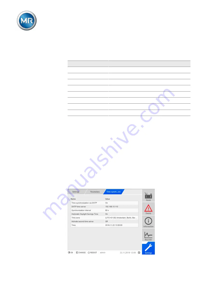
7.25 Time synchronization

You can set the the device time manually or automatically via an SNTP time
server. The device must be connected to an SNTP time server via Ethernet
for this purpose. You can set the following parameters:

▪ Time synchronization via SNTP

▪ Activate second time server (optional)

▪ SNTP time server (for the first and second SNTP time servers)

▪ Synchronization interval

▪ Time zone

▪ Automatic daylight saving / standard time

▪ Time (manual setting)

Figure 213: Setting time synchronization

Summary of Contents for ETOS IM

Page 1: ...Monitoring system ETOS IM Operating instructions 5163667 06 EN ...

Page 2: ... for compensation All rights reserved in the event of the granting of patents utility models or designs The product may have been altered since this document was published We reserve the right to change the technical data design and scope of supply Generally the information provided and agreements made when processing the individual quotations and orders are binding The original operating instruct...

Page 3: ...mental Safety Instructions 16 2 4 Personnel qualification 18 2 5 Personal protective equipment 19 3 IT security 21 4 Product description 25 4 1 Scope of delivery 25 4 2 Function description 26 4 2 1 Bushing monitoring 26 4 3 Performance features 27 4 4 Design 29 4 4 1 Power supply 30 4 4 2 Power supply 30 4 4 3 CPU central processing unit I 31 4 4 4 Voltage measurement and current measurement 32 4...

Page 4: ... rail 54 5 5 1 Fastening the cap rail 54 5 5 2 Installing the bus rail on the cap rail 55 5 5 3 Installing the assembly at a distance on the cap rail 56 5 6 Connecting device 57 5 6 1 Cable recommendation 58 5 6 2 Information about connecting serial interfaces RS232 and RS485 59 5 6 3 Notes on connecting to the MR sensor bus 61 5 6 4 Information about laying fiber optic cable 63 5 6 5 Mounting ter...

Page 5: ...et up automatic logout 97 7 3 Control optional 97 7 3 1 Setting the desired value 98 7 3 2 Bandwidth 111 7 3 3 Delay time T1 112 7 3 4 Delay time T2 114 7 4 Transformer data 116 7 4 1 Setting transformer data 116 7 4 2 Circuit examples for voltage transformers and current transformers 119 7 5 Measurement 133 7 5 1 Setting UI measuring channels 133 7 5 2 Control variable 133 7 5 3 Regulation mode 1...

Page 6: ...ues 168 7 10 2 Displaying measured value recorder optional 169 7 10 3 Setting the average value interval 173 7 10 4 Displaying temperature curve optional 174 7 10 5 Displaying winding temperatures optional 175 7 10 6 Displaying the measured values of the Buchholz relay optional 176 7 10 7 Displaying the measured values of the pressure relief device optional 177 7 10 8 Displaying the measured value...

Page 7: ...219 7 16 2 Managing sensors 222 7 16 3 Function assignment 223 7 16 4 Defining the sensors 224 7 16 5 Displaying information on the connected sensors 229 7 17 Configuring analog inputs and outputs optional 230 7 18 Configuring digital inputs and outputs 232 7 19 Name plate optional 234 7 19 1 Enter the name plate data 234 7 19 2 Displaying the name plate 235 7 20 Maintenance optional 235 7 20 1 Se...

Page 8: ...7 25 3 Setting the time zone 294 7 25 4 Setting synchronization interval 294 7 25 5 Automatic switchover between daylight saving time and standard time 295 7 25 6 Setting the date and time manually 295 7 26 User administration 295 7 26 1 User roles 295 7 26 2 Changing password 297 7 26 3 Creating editing and deleting users 298 7 26 4 Setting access rights to parameters and events 300 7 26 5 User a...

Page 9: ...IO 2 AIO 4 assembly 375 10 4 Uninstalling the DIO 28 15 DIO 42 20 assembly 377 10 5 Uninstalling the MC 2 2 SW 3 3 assembly 379 10 6 Uninstalling the QS3 241 assembly 381 10 7 Uninstalling the bus rail 382 10 8 Removing the bushing adapter and bushing coupling unit 383 11 Disposal 384 12 Technical data 385 12 1 Voltage supply 385 12 2 Voltage supply 385 12 3 Voltage measurement and current measure...

Page 10: ... GmbH 2019 10 5163667 06 EN ETOS IM 12 10 3 Connection cable 399 12 11 Ambient conditions 399 12 12 Standards and directives 400 13 Appendix 402 13 1 Check list for commissioning 402 13 2 Measured value log 403 Glossary 404 List of key words 406 ...

Page 11: ...9 Regensburg Germany Tel 49 9 41 40 90 0 Fax 49 9 41 40 90 7001 E mail sales reinhausen com Further information on the product and copies of this technical file are avail able from this address if required 1 2 Completeness This technical file is incomplete without the supporting documents The following documents are considered supporting documents Connection diagrams Supplement optional 1 3 Safeke...

Page 12: ...s relating to sec tions Embedded warnings use the following format DANGER Instruction for avoiding a dangerous situation 1 4 1 3 Signal words and pictograms The following signal words are used Signal word Definition DANGER Indicates a hazardous situation which if not avoided will result in death or serious injury WARNING Indicates a hazardous situation which if not avoided could result in death or...

Page 13: ...standing of particular procedures In this technical file it is laid out as follows Important information 1 4 3 Instruction system This technical file contains single step and multi step instructions Single step instructions Instructions which consist of only a single process step are structured as fol lows Aim of action ü Requirements optional Step 1 of 1 ð Result of step optional ð Result of acti...

Page 14: ...ventions The following typographic conventions are used in this technical file Typographic convention Purpose Example UPPERCASE Operating controls switches ON OFF Brackets PC keyboard Ctrl Alt Bold Software operating controls Press Continue button Menu paths Parameter Control parameter Italics System messages error messages signals Function monitoring alarm triggered Number of pages Cross referenc...

Page 15: ...sformers in the Um 123 420 kV voltage levels with voltage levels up to 765 kV on request You can use this func tion to detect breakdowns at partial capacitances in the bushing and to moni toring aging in the bushings If used as intended in compliance with the requirements and conditions specified in this technical file and observing the warning notices in this tech nical file and attached to the p...

Page 16: ... Unauthorized or inappropriate changes to the product may lead to per sonal injury material damage and operational faults Only modify product following discussion with Maschinenfabrik Reinhausen GmbH 2 3 Fundamental Safety Instructions To prevent accidents disruptions and damage as well as unacceptable ad verse effects on the environment those responsible for transport installa tion operation main...

Page 17: ... a microscope In the event that the laser beam strikes your eyes close your eyes imme diately and move your head out of the path of the beam Working with current transformers Dangerous high voltages may occur when a current transformer is operated with an open secondary circuit This can lead to injuries and property dam age Never operate a current transformer with an open secondary circuit short c...

Page 18: ...inspection must ensure that the personnel are sufficiently quali fied Electrically skilled person The electrically skilled person has a technical qualification and therefore has the required knowledge and experience and is also conversant with the ap plicable standards and regulations The electrically skilled person is also pro ficient in the following Can identify potential dangers independently ...

Page 19: ...orized by Maschinenfabrik Reinhausen GmbH to carry out the work Authorized personnel Authorized personnel are trained by Maschinenfabrik Reinhausen GmbH to carry out special maintenance 2 5 Personal protective equipment Personal protective equipment must be worn during work to minimize risks to health Always wear the personal protective equipment required for the job at hand Never wear damaged per...

Page 20: ...s To protect the eyes from flying parts and splash ing liquids Visor To protect the face from flying parts and splash ing liquids or other dangerous substances Hard hat To protect from falling and flying parts and mate rials Hearing protection To protect from hearing damage Protective gloves To protect from mechanical thermal and electri cal hazards ...

Page 21: ...r with the Operator role for example should only perform operative actions and should not be able to change any device settings Delete or disable the default admin user ID This requires first creating a new user account with the Administrator role You can then use it to delete or disable the default admin account Enable SSL TLS encryption Section 7 2 Page 94 access to the de vice is then only poss...

Page 22: ...1 2 TCP 80 Web visualization 1 ETH1 2 TCP 443 SSL protected web visualization ETH1 2 TCP 990 SSL protected FTP service access ETH1 2 TCP 8080 Web visualization alternative port 1 ETH1 2 TCP 8081 SSL protected web visualization alternative port Table 4 Interfaces and open ports of the OT1205 assembly 1 Port is closed if you activate the device s SSL encryption Figure 2 Interfaces of the CPU assembl...

Page 23: ...TH 2 x TCP 990 FTPS only for MR service ETH2 x TCP 8080 HTTP for web based visualization1 ETH2 x TCP 8081 HTTPS for web based visualization1 Table 5 Interfaces and open ports of the CPU assembly 1 Port is closed if you activate the device s SSL encryption 2 Default setting if you have modified the port for the control system proto col only the set port is opened Encryption standards The device sup...

Page 24: ...rity Maschinenfabrik Reinhausen GmbH 2019 24 5163667 06 EN ETOS IM 1 Not available with TLS version 1 2 The device uses the SHA256 hash function to save passwords Also refer to 2 Exporting data 306 2 General 94 ...

Page 25: ... for CAN bus optional Technical files Additional nameplate For the bushing monitoring option for each bushing to be monitored 3 or 6 Bushing adapter Connection cable for the bushing adapter and bushing coupling unit Bushing coupling unit Set of fasteners for the bushing coupling unit Connection cable for the bushing coupling unit and ISM control cabi net Please note the following Check the shipmen...

Page 26: ...to a control system SCADA ISM Signals SCADA Visualization via web browser Figure 3 Function description 4 2 1 Bushing monitoring The optional bushing monitoring function is used to monitor capacitance graded bushings on power transformers You can use the function to detect breakdowns at partial capacitances in the bushings and to monitor aging in the bushings In order to evaluate the state of the ...

Page 27: ...tor Temperature monitoring ambient temperature temperature of top oil temperature of bottom oil optional calculation of hot spot temperature in accordance with IEC 60076 7 or IEEE C57 91 Optional Transformer oil level Loss of life and relative aging rate Status of the motor drive unit motor protective switch motor is running Tap position display Optional Status of protective devices Buchholz relay...

Page 28: ...ing Bandwidth monitoring Function monitoring Limit value monitoring voltage current power phase angle Cooling system control 2 4 or 6 cooling stages can be individually parameterized Load dependent mode for early activation of cooling stages Periodic mode for regular activation of cooling stages Alternating mode for equal loading of similar cooling stages Cooling stage monitoring 2 4 or 6 cooling ...

Page 29: ...former Compensation for temperature fluctuations Compensation for the effects of weather Compensation for voltage fluctuations Compensation for grid asymmetry 4 4 Design Depending on the order the device is either designed as a 19 inch plug in housing or supplied as individual components for assembly on a cap rail The individual device assemblies are described in the following section Figure 5 19 ...

Page 30: ...mbly contains the power supply unit for powering the de vice Depending on configuration the device is equipped with one of the fol lowing power supply unit variants Multi voltage mains unit 85 265 V AC V DC DC voltage power supply unit 20 70 V DC 4 4 2 Power supply The G1 PULS DIMENSION QS3 241 assembly supplies power to the de vice Figure 7 G1 PULS DIMENSION QS3 241 assembly ...

Page 31: ...CPU central processing unit I The CPU I assembly is the central computing unit for the device It contains the following interfaces Internal system interface RS232 COM1 Serial interface RS232 485 COM2 3x Ethernet ETH1 ETH 2 1 ETH 2 2 USB USB 2 0 2x CAN bus CAN 1 CAN 2 Figure 8 CPU I assembly ...

Page 32: ...9 32 5163667 06 EN ETOS IM 4 4 4 Voltage measurement and current measurement The UI 1 assembly is used for measuring 1 phase voltage and current Figure 9 UI 1 assembly The UI 3 assembly is used for measuring 3 phase voltage and current Figure 10 UI 3 assembly ...

Page 33: ...42 inputs 20 outputs 8 N O contacts 12 change over contacts Figure 11 DIO 42 20 assembly 4 4 6 Analog inputs and outputs The AIO 2 and AIO 4 assemblies provide analog inputs and outputs AIO 2 2 channels AIO 4 4 channels In accordance with the device configuration the AIO assembly supports one of the following signal types Input Output Voltage Current Voltage Current 0 10 V 0 20 mA 4 20 mA 0 10 V 0...

Page 34: ...onverter which converts 2 electrical con nections RJ45 to one fiber optic cable connection each Each is converted independently of the other The following interfaces are available 2x RJ45 ETH12 ETH22 2x Duplex LC SFP module ETH11 ETH21 The media converter is designed to be transparent for the network and does not have its own IP address Figure 13 MC 2 2 assembly ...

Page 35: ...th the following inter faces A media converter converts an electric connection RJ45 into a fiber optic cable connection RJ45 ETH12 Duplex LC SFP module ETH11 Managed switch with redundancy function PRP or RSTP 2x RJ45 ETH23 ETH24 device internal connection 2x Duplex LC SFP module ETH21 ETH22 redundancy connection The following redundancy functions are available to you according to your order PRP s...

Page 36: ...ure 15 UI 5 3 assembly 4 4 10 Bus extension module The assemblies BEM 1 master and BES 1 slave are bus extension mod ules which are used to extend the system by one additional busbar with ad ditional assemblies Data is transmitted via fiber optic cable The assembly BES 1 has a connection for supplying voltage to the additional busbar Figure 16 Assemblies BEM 1 and BES 1 ...

Page 37: ...ose bushings The following components are used Bushing adapter A001 A008 C002 Bushing coupling unit Type Bushing types A001 Micafil RTKF Micafil RTKG A002 HSP SETFt 1550 420 1800 HSP SETFt 600 123 2000 A003 ABB GOB 1050 750 1100 0 6 B ABB GSA 123 OA 1600 0 5 ABB GSA 52 OA 2000 0 5 A004 Trench COT 750 800 A005 HSP SETFt 750 170 4000 HSP SETFt 1200 245 1250 HSP SETFt 1425 420 1600 HSP SESTFt 1050 24...

Page 38: ...schinenfabrik Reinhausen GmbH 2019 38 5163667 06 EN ETOS IM 4 5 Main screen The web based visualization is split into various areas Figure 17 Main screen 1 Display area 2 Secondary navigation 3 Primary navigation 4 Status bar ...

Page 39: ...s of the transformer shown can be selected directly when accessing via the web browser They act as links to the corresponding menu items If you are operating the device via the front panel you are only able to call up the elements via the Information menu Figure 18 Transformer data 1 DGA status 2 Temperature of top oil 3 Hot spot temperature 4 Load current and load voltage of phases L1 L2 L3 5 Tra...

Page 40: ...oil level and ambient temperature 1 Total apparent power 2 Ambient temperature 3 Oil level transformer on left on load tap changer on right Figure 20 On load tap changer and motor drive unit 1 OLTC oil temperature 2 Current tap position 3 Voltage regulator 4 Tap change operation statistics 5 Oil filter status ...

Page 41: ...mode On REMOTE Off LOCAL 2 AVR AUTO key Activate auto mode 2 RAISE key Send a control command to the motor drive unit to increase the voltage Only possible in manual mode 2 AVR Manual key Activate manual mode 2 LOWER key Send a control command to the motor drive unit to reduce the voltage Only possible in manual mode 1 Not available if local remote is toggled using a digital input 2 Only available...

Page 42: ...operate the device via the controls and visualization at the same time you have to log in on the device and via the visualization To log in as a user proceed as follows 1 Select the LOGIN or CHANGE button in the status line 2 Enter your user name and password and select the OK button ð The name of the logged in user appears in the status line To log out as a user proceed as follows Press the LOGOU...

Page 43: ...eters Time syn chronization Setting parameters There are various ways to configure the settings depending on the parame ter Selecting from a list To select a list entry proceed as follows 1 Use the rotary knob to navigate to the list and press the key Figure 22 Select an entry from a list 2 Use the rotary knob to highlight the list entry and press the key 3 Press the Accept button to save the modi...

Page 44: ... numerical keypad appears Figure 23 Entering a value 2 Enter the desired value and confirm with 3 Press the Accept button to save the modified parameter Entering text To enter text proceed as follows 1 Use the rotary knob to select the text box and press the key ð If operating via the front panel the keyboard appears Figure 24 Enter the text 2 Enter the desired text and confirm with 3 Press the Ac...

Page 45: ...me of the desired parameter in the Search entry field Figure 25 Quick search Expert mode The device has an expert mode for entering the parameters You can enter the parameters directly into the overview screen of the respective menu in this mode Figure 26 Expert mode To activate the expert mode proceed as follows 1 Go to Settings Parameters 2 Select the Expert mode checkbox ð Expert mode is active...

Page 46: ...scription Maschinenfabrik Reinhausen GmbH 2019 46 5163667 06 EN ETOS IM Hiding showing parameters Depending on how you set the parameters the device will hide or show ad ditional parameters related to this function ...

Page 47: ...ormer with an open secondary circuit short circuit the current transformer to prevent this Observe the information in the current transformer operating instructions NOTICE Damage to the device Electrostatic discharge may cause damage to the device Take precautionary measures to prevent the build up of electrostatic charges on work surfaces and personnel 5 1 Preparation The following tools are need...

Page 48: ...ded metal cable ducts Do not route lines which cause interference e g power lines and lines susceptible to interference e g signal lines in the same cable duct Maintain a distance of more than 100 mm between lines which cause in terference and those which are susceptible to interference Figure 27 Recommended wiring 1 Cable duct for lines causing inter ference 3 Cable duct for lines susceptible to ...

Page 49: ...e with EMC requirements Functional division of control cabinet physical separation Constant potential equalization all metal parts are joined Line routing in accordance with EMC requirements separation of lines which cause interference and those susceptible to interference Optimum shielding metal housing Overvoltage protection lightning protection Collective grounding main grounding rail Cable bus...

Page 50: ...otential equalization rail to equalize the poten tial If both devices have different potentials only connect the CAN bus cable shielding to one device Variant 1 The connected devices share the same potential If the devices to be connected share the same potential proceed as follows 1 Connect all devices to a potential equalization rail to equalize the poten tial 2 Connect the CAN bus cable shieldi...

Page 51: ...he following minimum distances to the control cabinet and to neighboring components Minimum distance To the floor of the control cabinet 88 9 mm 3 5 in Corresponds to 2 RU To the roof of the control cabinet Between assemblies on the bus bar and assem blies on the remote cap rail Table 9 Minimum distances in the control cabinet Figure 30 Example depiction of the minimum distances in a control cabin...

Page 52: ...ace device in 19 frame and screw down Figure 31 Example of device mounting in a 19 frame Mounting in a control panel with a 19 flush control panel frame optional To mount the device in a control panel proceed as follows ü Scope of delivery is complete Figure 32 Scope of delivery ...

Page 53: ...19 53 5163667 06 EN ETOS IM 1 Produce the cut out in the control panel Figure 33 Producing the cut out in the control panel 2 Mounting cage nuts Figure 34 Mounting cage nuts 3 Secure frame to control panel Figure 35 Securing frame to control panel ...

Page 54: ...r of flush control panel frame Figure 37 Closing cover 5 5 Installing the individual components on a cap rail 5 5 1 Fastening the cap rail The cap rail is required to mount a bus bar or a device s remote assemblies in a control cabinet Only use the following types of cap rails in accordance with EN 60715 TH 35 7 5 TH 35 15 The cap rail may not be painted or lacquered ...

Page 55: ...ear panel of the switch cabinet using screws and contact washers or lock washers The distance between the screws may be no more than 10 cm 3 94 in Figure 38 Fastening the cap rail 5 5 2 Installing the bus rail on the cap rail The bus rail connects the CPU DIO and AIO assemblies to each other me chanically and electrically The bus bar can contain different assemblies ac cording to your order Procee...

Page 56: ... following assemblies that must be mounted at a distance on the cap rail DIO 28 15 DIO 42 20 MC 2 2 SW 3 3 G1 PULS ü Cap rail fastened to the rear panel of the cabinet Section 5 5 1 Page 54 WARNING A faulty connection to the protective ground can lead to an electric shock in the event of faults Hook the assembly onto the cap rail at the specified location ensuring that the assembly engages cor rec...

Page 57: ... secondary terminals for the current transformer and voltage transformer Connect the output relays correctly to the motor drive unit Supply the voltage via separators and ensure that current paths can be short circuited Fit the separator clearly labeled close to the device s power supply so that it is freely accessible This ensures that the device can be re placed with ease in the event of a defec...

Page 58: ...ype Conductor cross sec tion Max length Power supply external OT1205 G1 PULS QS3 241 Unshielded 1 5 mm Power supply internal 24 VDC CPU DIO AIO MC SW Unshielded 1 5 mm Voltage measurement UI 1 UI 1 1 UI 3 Shielded 2 5 mm Current measurement UI 1 UI 1 1 UI 3 Unshielded 4 mm Signal inputs DIO 28 15 DIO 42 20 Shielded 1 5 mm2 400 m 25 Ω km Signal outputs DIO 28 15 DIO 42 20 Shielded 1 5 mm2 Signal in...

Page 59: ...nterfaces RS232 and RS485 NOTICE Damage to the device Using the wrong data cable may damage the device Only use data cables which comply with the description below RS232 D SUB 9 pole For connecting the device via the RS232 interface COM2 use a data cable with the following structure Figure 41 RS232 data cable 9 pole ...

Page 60: ...e with the following structure Figure 42 RS485 data cable D SUB 9 pole plug connection Only use 9 pole D SUB plugs with the following characteristics Plug housing is metallic or metal plated Cable shielding is connected with the plug using one of the two following variants Shielding is screwed down with traction relief Shielding is soldered with plug housing ...

Page 61: ...ss Observe the following notes for connecting the sensors NOTICE Damage to the device or sensor Connect all of the sensors to the potential equalization rail to avoid circulating currents over the MR sensor bus The MR sensor bus uses Modbus in a 2 wire configuration 2W The 4 wire configuration 4W is not supported They have to connect the sensors over a shielded line with 3 conductors D0 D1 Common ...

Page 62: ...A If you would like to use a MSENSE DGA sensor you must connect the sensor to the MR sensor bus with an M12 type A 5 pole plug connector in accordance with IEC 61076 2 101 If the MSENSE DGA sensor is the only bus node you must use a terminating resistor 120 Ω 0 5 W CPU COM2 MSENSE DGA D0 A D1 B Com C 1 2 3 4 5 6 7 8 9 D0 A D1 B Com C 1 4 2 3 5 1 2 3 4 5 D1 B D0 A Figure 45 Connection example MSENS...

Page 63: ...ection example MESSKO MTeC EPT303 FO on the MR sensor bus 5 6 4 Information about laying fiber optic cable To ensure the smooth transfer of data via the fiber optic cable you must en sure that mechanical loads are avoided when laying the fiber optic cable and later on during operation Also observe the information from the manufac turer of the fiber optic cable and the following instructions Radii ...

Page 64: ...or with terminating resistor provided as an option Figure 47 Terminating resistor of CAN bus 5 6 6 Connecting cables to the system periphery To obtain a better overview when connecting cables only use as many leads as necessary To connect cables to the system periphery proceed as follows ü Use only the specified cables for wiring Note the cable recommendation Connect the lines to be wired to the d...

Page 65: ... 65 5163667 06 EN ETOS IM 5 6 7 Wiring the CPU assembly 1 Connect the ETH 2 1 or ETH 2 2 optional interface to a PC in accor dance with the connection diagram to access the web based visualization Figure 48 Connection to a PC via Ethernet interface ...

Page 66: ...GmbH 2019 66 5163667 06 EN ETOS IM 2 Connect the ETH 1 interface to the control system SCADA in accor dance with the connection diagram Figure 49 SCADA connection Observe the information on connecting serial interfaces Section 5 6 2 Page 59 ...

Page 67: ...he control system SCADA in accordance with the connection diagram Figure 50 Serial SCADA connection via COM 2 interface Voltage supply You have to connect the CPU component to the voltage supply of the volt age supply unit Proceed as follows 1 Guide the leads into the plug terminal and fasten them using a screw driver Figure 51 Inserting the leads ...

Page 68: ...nto the respective 24 V DC slot Figure 52 Fastening the 24 V DC plug 5 6 8 Wiring the UI 1 UI 3 UI 5 assembly To wire the UI 1 UI 3 UI 5 assembly proceed as follows 1 Guide the leads into the corresponding plug terminals and fasten them us ing a screwdriver Figure 53 Example Plug for voltage measurement ...

Page 69: ...ots and engage the plug Figure 55 Engaging the plug 5 6 9 Wiring the AIO 2 AIO 4 AIO 8 assembly NOTICE Damage to the device and sensors Incorrectly connected and configured analog inputs outputs may result in damage to the device and sensor Follow information about connecting analog sensors Configure analog inputs and outputs according to the connected sensors ...

Page 70: ...e section with unshielded cables is kept as short as possible The shielding must be connected with shielding clips Figure 56 Examples of supporting shielding on ground bar on left Direct connection to AIO as sembly on right Connection using line up terminal Plug assignment The AIO 2 AIO 4 and AIO 8 assemblies have a separate plug connector for each channel input or output The plugs are assigned as...

Page 71: ...11 Analog inputs and outputs You can connect the following types of analog sensors 0 4 20 mA 0 10 V PT100 PT1000 2 wire 3 wire 4 wire 0 4 20 mA sensor You must connect a 4 20 mA sensor to the pins and You must also connect the supplied bridge to the pins and I OUT I U IN U OUT I U IN I U OUT 1 2 3 4 5 4 20 mA signal source Figure 58 Connection example for a 4 20 mA sensor PT100 PT1000 sensor Depen...

Page 72: ...OUT I U IN U OUT I U IN I U OUT 1 2 3 4 5 3 wire I OUT I U IN U OUT I U IN I U OUT 1 2 3 4 5 4 wire PT100 PT1000 Figure 59 Connection example for a PT100 PT1000 sensor Wiring analog inputs outputs 1 Guide the leads into the plug terminal and fasten them using a screw driver Figure 60 Inserting the leads into the plug connector ...

Page 73: ...e slot in accordance with the supplied connection diagram Figure 61 Fastening the plug analog inputs outputs Voltage supply Connect the AIO 2 AIO 4 AIO 8 assembly to the voltage supply of the volt age supply unit 1 Guide the leads into the plug terminal and fasten them using a screw driver Figure 62 Inserting the leads ...

Page 74: ...rt and fasten the plug into the respective 24V DC slot Figure 63 Fastening the 24 V DC plug 5 6 10 Wiring the DIO assembly 1 Guide the leads into the plug terminal in accordance with the supplied connection diagram and fasten them using a screwdriver Figure 64 Inserting the leads ...

Page 75: ...the DIO 28 15 DIO 42 20 assemblies to CPU I using the CAN bus cable When connecting the DIO 28 15 DIO 42 20 assembly to the CPU assembly it is imperative that you use only the supplied connection cable If you use the 2 1 m or 3 m connection cable you must insert the plug with the CPU label into the CPU assembly because this plug contains a terminating resis tor If you are using shorter cables you ...

Page 76: ...Figure 66 CAN bus connection Voltage supply Connect the DIO 28 15 DIO 42 20 assembly to the voltage supply of the voltage supply unit 1 Guide the leads into the respective plug terminals for the voltage supply and fasten them using a screwdriver Figure 67 Inserting the leads ...

Page 77: ...Setting rotary switches of DIO 28 15 and DIO 42 20 If the device has 2 DIO assemblies you have to ensure that the L rotary switches have different settings on the respective assemblies This is the only way of ensuring a perfect CAN bus connection DIO H L First assembly DIO 28 15 DIO 42 20 0 1 Second assembly DIO 28 15 1 DIO 42 20 1 0 2 Table 12 Rotary switch configuration ...

Page 78: ...OS IM Figure 69 Rotary switch H and L of DIO assembly 5 6 11 Wiring the MC 2 2 SW3 3 assembly 1 Insert the supplied SFP module into the corresponding Ethernet interface in accordance with the connection diagram and fold the clasp down Figure 70 Engaging the SFP module ...

Page 79: ...hinenfabrik Reinhausen GmbH 2019 79 5163667 06 EN ETOS IM 2 Remove the SFP module dust plug Figure 71 Removing the dust plug 3 Insert the fiber optic cable into the SFP module Figure 72 Inserting the fiber optic cable ...

Page 80: ...etwork cable Figure 73 Inserting the network cable Voltage supply Connect the MC2 2 SW3 3 assembly to the voltage supply of the voltage supply unit 1 Guide the leads into the respective plug terminals for the voltage supply and fasten them using a screwdriver Figure 74 Inserting the leads ...

Page 81: ...and damage to the device There is a fire hazard if the cables for the 24 V supply to the assemblies are insufficiently dimensioned This can lead to severe burns and property dam age Only use cables with a cross section of 1 5 mm The G1 PULS assembly is to be used exclusively for supplying the assem blies of this product and the cable routing is to be as short as possible ca ble length max 2 5 m Ot...

Page 82: ...embly in accordance with the connection dia gram 1 Insert the leads into the corresponding connections and close the lever Figure 76 Inserting the leads 2 Insert the leads of the neutral conductor N phase conductor L and pro tective conductor into the corresponding connections and close the lever ...

Page 83: ...tage maximum currents when selecting the circuit breaker type In addition observe the following It must be easy for the operator to access the isolating device The isolating device must be labeled for the device and circuits to be iso lated The isolating device may not be a part of the power line The isolating device may not interrupt the main protective conductor Miniature circuit breaker You mus...

Page 84: ...chinenfabrik Reinhausen GmbH 2019 84 5163667 06 EN ETOS IM Connecting the voltage supply To connect the voltage supply proceed as follows Connect the voltage supply in accordance with the connection diagram provided ...

Page 85: ...tire configuration before commissioning 6 1 Performing tests Please contact Maschinenfabrik Reinhausen GmbH MR if any aspect of the tests is not clear 6 1 1 Ground test For commissioning carry out a ground test check of the impedance of the protective bonding in accordance with IEC 61010 1 Note the following in formation Test current 2 times the measurement current of the overcurrent protec tion d...

Page 86: ...and the protective conductor ð The measured voltage must remain less than 10 V over a duration of 1 minute Figure 78 Perform a ground test on the DIO assembly sample representation of the DIO 28 15 assembly 2 Feed the test current at the grounding terminal of the G1 PULS DIMEN SION QS3 241 assembly using a constant current source and measure the voltage between the measurement point and the protec...

Page 87: ...to the device being damaged Perform the dielectric test with a test voltage that is less than or equal to the maximum permitted test voltage Perform the dielectric test using the permitted interfaces only Depending on the device configuration you may only test the assemblies listed below You may not test any other assemblies Assembly Interfaces Test parameters Max test voltage Max test dura tion R...

Page 88: ...2 20 HL any DI DO 2 2 kV AC 2 s 5 s 1 mA G1 PULS N L 2 2 kV AC 2 s 5 s 4 mA Table 13 Permitted interfaces and test parameters for the dielectric test 1 only the version with 85 265 VAC VDC wide range power supply other wise the device may be damaged Note the nameplate Sample dielectric test set up Figure 80 Sample set up of the dielectric test for a device designed with the OT 1205 wide range powe...

Page 89: ...ith a maximum of 4 languages The following languages are available English Italian German Portuguese French Russian Spanish Chinese Korean Language is available as an option To set the language proceed as follows 1 Select the Language button in the status bar or as an alternative go to Settings General Language Figure 82 Setting the language 2 Select the language you want from the list box 3 Press...

Page 90: ...mation provided in the Time synchroniza tion Section 7 25 Page 292 section 6 4 Commissioning wizard If you want the device to help when setting the relevant parameters you can use the commissioning wizard The commissioning wizard provides a selec tion of parameters that you can configure in order A detailed description of each of the parameters can be found in the Opera tion Section 7 Page 92 chap...

Page 91: ...and status of digital inputs and outputs Upon commissioning the device check whether the measured values and status of digital inputs and outputs are plausible To do so use an additional measuring device if necessary in order to check the individual measured val ues To display the status of the digital inputs and outputs proceed as follows 1 Go to Information Hardware 2 Select the individual assem...

Page 92: ...te display control center etc Establishing connection via front interface The device is equipped with a DHCP server for connection via the front inter face To establish a connection via the front interface proceed as follows 1 Connect PC and device via front interface using Ethernet cable RJ45 plug Figure 84 Establishing connection via the front interface 2 Activate automatic assignment of the IP ...

Page 93: ...ace on the back proceed as follows 1 Connect PC and device via ETH2 2 interface on back using Ethernet ca ble RJ45 plug Figure 85 Establishing connection via the ETH2 2 interface on the back 2 Go to Communication on the device to display the device s IP address Figure 86 Displaying Communication 3 Assign the PC an unique IP address in the same subnet as the device e g 192 0 1 100 ...

Page 94: ...ou can use these parameters to undertake the network configuration for the visualization These settings apply to access via the ETH2 2 interface on the CPU module Assign IP addresses to both web based visualization and SCADA optional in different subnets Otherwise you will not be able to establish a connec tion 1 Go to Settings Parameters General IP address Subnet mask or Gateway 2 Enter the desir...

Page 95: ...sired option 3 Press the Accept button to save the modified parameter 7 2 2 Activating deactivating automatic launch of commissioning wizard You can use this parameter to set whether the commissioning wizard Section 6 4 Page 90 is to launch automatically when the device is restarted 1 Go to Settings Parameters General Commissioning wizard 2 Select the desired option 3 Press the Accept button to sa...

Page 96: ...CADA Table 15 Selecting Remote behavior To set the Remote behavior proceed as follows 1 Go to Settings Parameters General Remote behavior 2 Select the desired option 3 Press the Accept button to save the modified parameter 7 2 6 Accessing online help The web based visualization has an online help section To call up the online help proceed as follows 1 Call up the web based visualization with the P...

Page 97: ...ction for a user then this user will not be automatically logged out To set automatic logout proceed as follows 1 Go to Settings Parameters General 2 Select the desired parameter 3 Set parameter 4 Press the Accept button to save the modified parameter Auto logout You can use this parameter to activate automatic logout monitoring Time until auto logout You can use this parameter to set the time per...

Page 98: ...ia digital inputs or the control sys tem when it is in the Remote mode You must also set the Remote behavior Section 7 2 5 Page 96 parameter accordingly Setting the desired value To set the desired value proceed as follows 1 Go to Settings Parameters Control Desired value 2 Enter desired value 3 Press the Accept button to save the modified parameter Selecting a desired value You can use this param...

Page 99: ...lue You can use this parameter to select the desired value used for control To select the desired value proceed as follows 1 Go to Settings Parameters Control Select desired value 2 Select the desired value you want in the list 3 Press the Accept button to save the modified parameter 7 3 1 4 Analog setting of the desired value With the analog setting of the desired value the desired value for the ...

Page 100: ...t the desired value that corresponds to the minimum level of the analog signal e g 4 mA for 4 20 mA signal 1 Go to Settings Parameters Control Setting min desired value 2 Enter desired value 3 Press the Accept button to save the modified parameter 7 3 1 5 Step by step setting of the desired value For the step by step setting of the desired value you can increase or de crease the desired value for ...

Page 101: ...g increased load or an in crease in voltage due to a decentralized feed in Depending on whether positive or negative active power is measured the desired value calculation is based on 2 linear equations see example in dia gram below Parameter Function Settings see diagram below Umax Maximum desired value Maximum set desired value is activated when Pmax is exceeded 103 0 V Umin Minimum desired valu...

Page 102: ...ive power at minimum de sired value U0 Set desired value when mea sured active power 0 Pmax Active power at maximum de sired value Response to active power Pmax being exceeded If the measured active power Pmeas exceeds the set parameter Pmax the value Umax is adopted as the desired value Response to value falling below active power Pmin If the measured active power Pmeas falls below the set parame...

Page 103: ...wing parameters Activating TDSC The TDSC function is only active when the device can calculate the active power correct current measurement and voltage measurement and the re quired parameters are set If this isn t done the voltage is regulated to the set desired value Section 7 3 1 1 Page 98 You can activate or deacti vate the power dependent adjustment of the desired voltage value as fol lows Pa...

Page 104: ...ttings Parameters Control TDSC Pmax Pmin 2 Enter active power for maximum minimum desired value 3 Press the Accept button to save the modified parameter 7 3 1 7 Active power dependent adjustment of desired voltage value with 3 different desired values The TAPCON Dynamic Setpoint Control TDSC function is used to adapt the desired voltage value depending on the measured active power This al lows you...

Page 105: ... value below which the power dependent desired value is to attain the mini mum value Umin 20 0 MW Table 17 Parameters to be set for active power dependent adjustment of desired voltage value Figure 90 Active power dependent adjustment of desired voltage value Uref Desired value Umin Minimum desired value Pmeas Measured active power Umax Maximum desired value Pmin Active power at minimum de sired v...

Page 106: ... with positive active power If the measured active power 0 Pmeas Pmax the desired value is calculated using the following formula To activate the active power dependent adjustment of the desired voltage value you need to set the following parameters Activating TDSC The TDSC function is only active when the device can calculate the active power correct current measurement and voltage measurement an...

Page 107: ...1 2 3 U0 You can use this parameter to set the desired value which is to be used when the measured active power is 0 1 Go to Settings Parameter Control TDSC U0 2 Enter desired value at active power 0 3 Press the Accept button to save the modified parameter TDSC 1 2 3 Pmax Pmin You can use these parameters to set the maximum and minimum active power value at which the maximum and minimum active pow...

Page 108: ...device uses the value set in parameter desired value 1 Desired value BCD input 100 80 40 20 10 8 4 2 1 49 V 0 0 1 0 0 1 0 0 1 50 V 0 0 1 0 1 0 0 0 0 51 V 0 0 1 0 1 0 0 0 1 52 V 0 0 1 0 1 0 0 1 0 53 V 0 0 1 0 1 0 0 1 1 54 V 0 0 1 0 1 0 1 0 0 55 V 0 0 1 0 1 0 1 0 1 56 V 0 0 1 0 1 0 1 1 0 57 V 0 0 1 0 1 0 1 1 1 58 V 0 0 1 0 1 1 0 0 0 59 V 0 0 1 0 1 1 0 0 1 60 V 0 0 1 1 0 0 0 0 0 61 V 0 0 1 1 0 0 0 0 ...

Page 109: ...0 1 1 0 87 V 0 1 0 0 0 0 1 1 1 88 V 0 1 0 0 0 1 0 0 0 89 V 0 1 0 0 0 1 0 0 1 90 V 0 1 0 0 1 0 0 0 0 91 V 0 1 0 0 1 0 0 0 1 92 V 0 1 0 0 1 0 0 1 0 93 V 0 1 0 0 1 0 0 1 1 94 V 0 1 0 0 1 0 1 0 0 95 V 0 1 0 0 1 0 1 0 1 96 V 0 1 0 0 1 0 1 1 0 97 V 0 1 0 0 1 0 1 1 1 98 V 0 1 0 0 1 1 0 0 0 99 V 0 1 0 0 1 1 0 0 1 100 V 1 0 0 0 0 0 0 0 0 101 V 1 0 0 0 0 0 0 0 1 102 V 1 0 0 0 0 0 0 1 0 103 V 1 0 0 0 0 0 0 1...

Page 110: ...1 0 123 V 1 0 0 1 0 0 0 1 1 124 V 1 0 0 1 0 0 1 0 0 125 V 1 0 0 1 0 0 1 0 1 126 V 1 0 0 1 0 0 1 1 0 127 V 1 0 0 1 0 0 1 1 1 128 V 1 0 0 1 0 1 0 0 0 129 V 1 0 0 1 0 1 0 0 1 130 V 1 0 0 1 1 0 0 0 0 131 V 1 0 0 1 1 0 0 0 1 132 V 1 0 0 1 1 0 0 1 0 133 V 1 0 0 1 1 0 0 1 1 134 V 1 0 0 1 1 0 1 0 0 135 V 1 0 0 1 1 0 1 0 1 136 V 1 0 0 1 1 0 1 1 0 137 V 1 0 0 1 1 0 1 1 1 138 V 1 0 0 1 1 1 0 0 0 139 V 1 0 0 ...

Page 111: ... be known Note that a large bandwidth will result in a large control deviation The bandwidth must always be greater than the following value Figure 91 Calculation of minimum bandwidth Un 1 Step voltage of tap position n 1 Un Step voltage of tap position n Unom Nominal voltage The following transformer values are used to determine the minimum band width Nominal voltage Unom 11 000 V Step voltage in...

Page 112: ...hin the set delay time T1 However if the measured voltage deviates from the set bandwidth for a long period a tap change command occurs after expiration of the set delay time T1 The on load tap changer carries out a tap change in a raise or lower direction to return to the tolerance bandwidth Figure 92 Behavior of the regulation function with delay time T1 1 B Upper limit 4 Set delay time T1 2 Ude...

Page 113: ...me regardless of the control deviation Integral time response With integral time response the device responds with a variable delay time depending on the control deviation The greater the control deviation ΔU in relation to the set bandwidth B the shorter the delay time This means that the device responds faster to large voltage changes in the grid Regulation accuracy improves as a result but the ...

Page 114: ...et delay time T1 After the set tap change delay time T2 has elapsed additional pulses occur in order to correct the existing control deviation The following requirements must be noted to set delay time T2 The delay time T2 must be greater than the switching pulse time The delay time T2 must be greater than the maximum operating time of the motor drive unit The delay time T2 must be less than the v...

Page 115: ...ce bandwidth Figure 94 Behavior of the regulation function with delay times T1 and T2 1 B Upper limit 4 Set delay times T1 and T2 2 Udesired Desired value 5 Uactual Measured voltage 3 B Lower limit 6 B Tolerance bandwidth A Uactual is outside the bandwidth De lay time T1 starts B Delay time T1 complete Tap change triggered C Delay time T2 complete Tap change triggered Setting delay time T2 To set ...

Page 116: ... are then displayed 7 4 1 Setting transformer data You can use the following parameters to set the transformer data Also note the Examples for standard circuits for current transformers and voltage transformers Section 7 4 2 Page 119 Figure 95 Setting transformer data Primary transformer voltage With this parameter you can set the primary voltage of the voltage trans former in kV To set the primar...

Page 117: ...arameter Secondary transformer current You can use this parameter to set the secondary current of the current trans former You can select the following options 0 2 A 1 A 5 A If you use the optional function Hot spot calculation on 3 different windings W1 W2 W3 the setting of this parameter applies to all 3 windings To set the secondary transformer current proceed as follows 1 Go to Settings Parame...

Page 118: ...Ph phase voltage Measurement in 3 phase grid between conductor and neutral conductor Table 19 Voltage transformer circuit To set the voltage transformer circuit proceed as follows 1 Go to Settings Parameters Transformer data Voltage trans former circuit 2 Select the desired option 3 Press the Accept button to save the modified parameter Current transformer circuit You can use this parameter to set...

Page 119: ...he current transformer circuit W2 W3 proceed as follows 1 Go to Settings Parameters Transformer data Current trans former circuit W2 W3 2 Select the desired option 3 Press the Accept button to save the modified parameter 7 4 2 Circuit examples for voltage transformers and current transformers Below you will find different examples of circuits for voltage transformers and current transformers and t...

Page 120: ...1 B The voltage transformer VT is connected to the phase conductor L1 and the neutral conductor The current transformer CT is looped into the phase conductor L1 The voltage U and current I are in phase The voltage drop on a phase conductor is determined by the current IL1 If you use this circuit set the device as follows Parameter Option Voltage transformer circuit 3 Ph phase voltage Current trans...

Page 121: ... the device as follows Parameter Option Voltage transformer circuit 3 Ph differential voltage Current transformer circuit 3 Ph total current Phase angle correction 0 Table 24 Circuit 1 C Circuit 1 D The voltage transformer VT is connected to the phase conductors L1 and L2 The current transformer CT is looped into the phase conductor L3 The current IL3 is ahead of voltage UL1 VL2 by 90 This corresp...

Page 122: ...d by the current IL2 If you use this circuit set the device as follows Parameter Option Voltage transformer circuit 3 Ph differential voltage Current transformer circuit 3 Ph phase current Phase angle correction 30 Table 26 Circuit 1 E Circuit 1 F The voltage transformer VT is connected to the phase conductors L1 and L2 The current transformer CT is looped into the phase conductor L1 The current I...

Page 123: ...e correction 30 Table 27 Circuit 1 F 7 4 2 2 3 phase measurement Circuit 3 A Three phase measurement The voltage transformers are connected between the phases The current lags behind the voltage by 30 If you use this circuit set the device as follows Parameter Option Voltage transformer circuit Current transformer circuit Phase angle correction 0 UI measuring channels 3 phase measurement channels ...

Page 124: ...mer circuit Phase angle correction 0 UI measuring channels 3 phase measurement channels 1 2 3 Measurement mode Phase neutral Table 29 Circuit 3 B Only use the circuits 3 C 3 D and 3 E on symmetrical grids Otherwise the device will calculate incorrect performance values Circuit 3 C Three phase voltage measurement single phase current measurement The voltage transformers are connected between the ph...

Page 125: ...voltage 1 ph current Measurement mode Phase phase Table 30 Circuit 3 C Circuit 3 D Three phase voltage measurement single phase current measurement The voltage transformers are connected between the phases The current transformer is connected to phase L2 Parameter Option Voltage transformer circuit Current transformer circuit Phase angle correction 150 UI measuring channels 3 ph voltage 1 ph curre...

Page 126: ...ransformer circuit Current transformer circuit Phase angle correction 90 UI measuring channels 3 ph voltage 1 ph current Measurement mode Phase phase Table 32 Circuit 3 E Circuit 3 F Three phase voltage measurement single phase current measurement The voltage transformers are connected between the phase and neutral conductor The current transformer is connected to phase L1 Parameter Option Voltage...

Page 127: ...phase voltage measurement single phase current measurement The voltage transformers are connected between the phase and neutral conductor The current transformer is connected to phase L2 Parameter Option Voltage transformer circuit 3 Ph phase voltage Current transformer circuit 3 Ph phase current Phase angle correction 120 UI measuring channels 3 ph voltage 1 ph current Measurement mode Phase neut...

Page 128: ...mode Phase neutral Table 35 Circuit 3 H 7 4 2 3 Special applications The following circuits S 1 S 2 S 3 and S 4 describe special cases of cur rent measurement for hot spot calculation on 3 different windings e g three winding transformer or transformer with tertiary winding Only use these circuits in symmetrical grids Note that you must always take the W1 voltage and current measurements on the lo...

Page 129: ...vice as follows Parameter Option Voltage transformer circuit Current transformer circuit 3 Ph phase current Current transformer circuit W2 Total current Current transformer circuit W3 Phase current Phase angle correction 0 UI measuring channels 3 ph voltage 1 ph current Measurement mode Phase neutral Table 36 Circuit S 1 ...

Page 130: ...e as follows Parameter Option Voltage transformer circuit 3 Ph phase voltage Current transformer circuit 3 Ph phase current Current transformer circuit W2 Total current Current transformer circuit W3 Phase current Phase angle correction 0 UI measuring channels 1 ph measurement Channel 1 Measurement mode Table 37 Circuit S 2 ...

Page 131: ...evice as follows Parameter Option Voltage transformer circuit Current transformer circuit 3 Ph phase current Current transformer circuit W2 Phase current Current transformer circuit W3 Phase current Phase angle correction 0 UI measuring channels 3 ph voltage 1 ph current Measurement mode Phase phase Table 38 Circuit S 3 ...

Page 132: ... follows Parameter Option Voltage transformer circuit 3 Ph differential voltage Current transformer circuit 3 Ph phase current Current transformer circuit W2 Phase current Current transformer circuit W3 Phase current Phase angle correction 30 UI measuring channels 1 ph measurement Channel 1 Measurement mode Table 39 Circuit S 4 ...

Page 133: ...e ment and 1 channel for current measurement Table 40 UI measuring channels To set the UI measuring channels proceed as follows 1 Go to Settings Parameters Measurement UI measuring chan nels 2 Select the option you want 3 Press the Accept button to save the modified parameter 7 5 2 Control variable If you are measuring the voltage and current with the 3 phase UI 3 measur ing module and using the s...

Page 134: ...ion option automatic voltage regu lation is blocked should the voltage or current measurement of one of the 3 phases fail To set the regulation mode proceed as follows 1 Go to Settings Parameters Measurement Regulation mode 2 Select the option you want 3 Press the Accept button to save the modified parameter 7 5 4 Setting the display for the power factor This parameter lets you set whether the dev...

Page 135: ...ents of the motor drive unit s controller Setting the switching pulse time You can use the switching pulse time parameter to set the maximum dura tion of the switching pulse It resets after the switching pulse time has elapsed or if the device receives the Motor running signal beforehand or the tap position is changed To set the switching pulse time proceed as follows 1 Go to Settings Parameters M...

Page 136: ...time is exceeded the device triggers the follow ing actions 1 Motor runtime exceeded event 2 Pulse signal via Trigger motor protective switch output relay Note that motor drive units with cycle settings or motor drive units without stepped switching behavior will run for longer under certain circumstances Set a longer motor runtime for such units The following parameters are available to configure...

Page 137: ...ttings Parameters Motor control Switching direction 2 Select the option you want 3 Press the Accept button to save the modified parameter 7 7 Parallel operation optional Parallel transformer operation is used to increase the throughput capacity or short circuit capacity at one location The device provides you with specific functions for regulating transformers Conditions for parallel operation Com...

Page 138: ...s own tap change operation The devices then ei ther change position sequentially first the master then the followers or in synch master and followers at the same time If there is a tap difference between the master and followers the master re frains from issuing any control commands to the motor drive unit until all of the followers have reached the same tap position If the tap difference per sist...

Page 139: ...ation is carried out using the circulating reactive current minimization method U I cosφ CAN bus M AVR M AVR T1 T2 Figure 98 Circulating reactive current minimization with CAN bus communication The circulating reactive current is calculated from the transformer currents and their phase angles The voltage regulators in the parallel operation group share this information via CAN bus An extra control...

Page 140: ...ofit TAPCON 2xx Section 7 7 3 Page 147 param eter For the circulating reactive current minimization parallel operation method with CAN communication you have to set the following parameters Activate parallel operation Parallel operation method Circulating reactive current CAN bus address Circulating reactive current sensitivity Circul reactive current blocking limit Error if no communication prese...

Page 141: ...correctly set the device parameters The power factor method is suited to transformers connected in parallel with a similar nominal output and short circuit voltage UK and to vector groups with the same and different step voltages This does not require any informa tion about the tap position For the circulating reactive current minimization parallel operation method without CAN communication you ha...

Page 142: ... parallel operation The following sections describe how you can set the parameters 7 7 2 1 Activating parallel operation You can use this parameter to activate or deactivate parallel operation To activate or deactivate parallel operation proceed as follows 1 Go to Settings Parameters Parallel operation Activate parallel operation 2 Select the option you want from the list field 3 Press the Accept ...

Page 143: ... Page 139 parallel op eration method Power factor Circulating reactive current minimization without CAN bus communication Section 7 7 1 3 Page 140 parallel op eration method Table 44 Setting parallel operation method Only change the parallel operation method when the on load tap changers are not performing tap change operations To select the parallel operation method proceed as follows 1 Go to Set...

Page 144: ...the current transformer If during parallel operation the circulating reactive cur rent exceeds the set limit value the device triggers the Circulating reactive current blocking limit exceeded event All devices operating in the parallel operation group are blocked To set the circulating reactive current blocking limit proceed as follows 1 Go to Settings Parameters Parallel operation Circulating rea...

Page 145: ...llel operation Desired load stress type 2 Select the desired load stress type 3 Press the Accept button to save the modified parameter 7 7 2 8 Setting master follower current blocking You can use this parameter to activate the circulating reactive current block ing limit for the tap synchronization parallel operation method The device thereby calculates and monitors the circulating reactive curren...

Page 146: ...the option you want 3 Press the Accept button to save the modified parameter 7 7 2 10 Setting the maximum tap difference You can use this parameter to set the maximum permissible tap difference between followers and master on the follower If the tap difference is greater than the set maximum tap difference to the master the follower blocks and no longer attempts to attain the master s tap position...

Page 147: ...ethod Table 45 Behavior if no communication present To set the behavior proceed as follows 1 Go to Settings Parameters Parallel operation Behavior if no communication present 2 Select the desired option 3 Press the Accept button to save the modified parameter 7 7 2 13 Setting delay time for parallel operation error messages You can use this parameter to set the delay time for a parallel operation ...

Page 148: ... correction 1 Go to Settings Parameters TAPCON 2xx retrofit TAPCON 2xx retrofit 2 Select the option you want 3 Press the Accept button to save the modified parameter 7 7 4 Detecting parallel operation via group inputs optional You can control up to 16 transformers connected in parallel in one or 2 groups without detecting the system topology The devices in parallel operation only use the informati...

Page 149: ...the measured value is higher than the upper limit or or lower than the lower limit or the device reacts in accordance with the Behavior parameter U U U t U U tV tE H Figure 103 Example of voltage monitoring with the limit value Overvoltage U being exceeded U Overvoltage U U Overvoltage U U Undervoltage U U Undervoltage U tV Delay time tE Event duration H Hysteresis You can set the following parame...

Page 150: ...imit value in relative to the de sired voltage value Limit value V or kV Absolute limit value You can use this parameter to specify an absolute limit value in V in relation to the secondary value of the voltage transformer or in kV in relation to the primary value of the voltage transformer Unlike the relative value this limit is not dependent on a reference value Limit value Limit value relative ...

Page 151: ...on U until the mea sured voltage is back above the limit value For U U The device performs tap change opera tions in the lower voltage direction U until the mea sured voltage is back below the limit value With high speed return the device ignores the set delay time T1 of automatic voltage regulation Auto blocking An event message is issued Automatic regulation is blocked Auto manual blocking An ev...

Page 152: ...e 105 Example of current monitoring with the limit value I being exceeded I Upper limit 2 I Upper limit 1 I Lower limit 1 I Lower limit 2 tV Delay time tE Event duration H Hysteresis You can set the following parameters for each limit value Relative absolute limit value Limit value A or kA Absolute limit value Limit value Limit value relative to rated current of current transformer Hysteresis limi...

Page 153: ...ses the relative limit value in relative to the rated current of current transformer Limit value A or kA Absolute limit value You can use this parameter to specify an absolute limit value in A in relation to the secondary value of the current transformer or in kA in relation to the primary value of the current transformer Limit value Limit value relative to rated current of current transformer You...

Page 154: ...ation is blocked Auto manual blocking An event message is issued Automatic regulation is blocked You cannot perform tap change operations in manual mode Table 47 Behavior when an event message is issued 7 8 3 Power monitoring For monitoring the transformer s current power you can set the following limit values Measured value Lower limit 2 Lower limit 1 Upper limit 1 Upper limit 2 Apparent power S ...

Page 155: ...to save the modified parameter Limit value Absolute limit value You can use this parameter to specify a limit value Hysteresis limit value You can use this parameter to set the hysteresis You can use this to avoid the unnecessary generation of messages if the measured value fluctuates around a threshold value Delay time limit value You can use this parameter to set the delay time in order to delay...

Page 156: ...unnecessary generation of messages if the measured value fluctuates around a threshold value Setting the delay time You can use this parameter to set the delay time in order to delay the issuing of the Reversal of power flow message Setting the behavior You can use this parameter to set the behavior in the event of a reversal of power flow You can select the following options Setting Behavior Off ...

Page 157: ...ensation is activated this function is deacti vated The device triggers a tap change operation to the tap position you defined in the Target tap posi tion Section 7 9 Page 168 parameter The device blocks further tap change operations The target tap position operation is ignored if there is no tap position capture Automatic regulation is blocked Table 49 Behavior in the event of a reversal of power...

Page 158: ...higher tap position position You cannot perform a tap change operation in the direction of a higher tap position position in manual mode Auto manual blocking position The automatic control does not perform a tap change operation in the direction of a lower tap position position You cannot perform a tap change operation in the direction of a lower tap position position in manual mode Operations cou...

Page 159: ...ll below the bandwidth indicate a problem with the device function be cause the device is not able to correct the control deviation Behavior If the value falls below or exceeds the set bandwidth Section 7 3 2 Page 111 the Function monitoring event is displayed after the set delay time for function monitoring has elapsed The event is automatically acknowledged as soon as the measured value returns ...

Page 160: ... use this to avoid the unnecessary generation of messages if the measured value fluctuates around a threshold value Delay time limit value You can use this parameter to set the delay time in order to delay the issuing of the event message Also refer to 2 Current monitoring 151 7 8 7 Phase symmetry monitoring If you are measuring the voltage and current with the 3 phase UI 3 measur ing module you c...

Page 161: ...Accept button to save the modified parameter U 3ph You can use this parameter to specify a limit value for the voltage difference in V in relation to the secondary value of the voltage transformer or in kV in relation to the primary value of the voltage transformer φ 3ph You can use this parameter to specify a limit value for the phase angle differ ence U 3ph φ 3ph delay time You can use this para...

Page 162: ... perform tap change operations in manual mode Table 51 Behavior when an event message is issued 7 8 8 Temperature monitoring You can set different limit values for every measured calculated temperature If the measured temperature is greater than limit value or the device triggers an event message If the measured temperature is less than limit value or the device triggers an event message Figure 11...

Page 163: ...g rate is greater than the limit value the device triggers an event Figure 112 Tx statistics monitoring To set the limit values proceed as follows 1 Go to Settings Parameters Tx statistics monitoring 2 Select the parameter you want 3 Set the parameter you want 4 Press the Accept button to save the modified parameter Displaying transformer statistics To display the transformer statistics proceed as...

Page 164: ...the on load tap changer has multiple columns you can set 2 limit values for each column If the measured gas volume is greater than the limit value or the device triggers an event message Figure 114 Limit values for the gas volume of the Buchholz relay of the on load tap changer To set the limit values proceed as follows 1 Go to Settings Parameters On load tap changer Buchholz relay 2 Select the de...

Page 165: ... limit values for the gas volume If the measured gas volume is greater than the limit value or the device triggers an event message Figure 115 Limit values for the gas volume of the Buchholz relay of the transformer To set the limit values proceed as follows 1 Go to Settings Parameters Active part Buchholz relay 2 Select the desired parameter 3 Set the desired parameter 4 Press the Accept button t...

Page 166: ...et 2 limit values for the gas volume If the mea sured oil pressure is greater than the limit value or the device triggers an event message Figure 116 Limit values for the oil pressure of the transformer To set the limit values proceed as follows 1 Go to Settings Parameters Active part Pressure relief device 2 Select the desired parameter 3 Set the desired parameter 4 Press the Accept button to sav...

Page 167: ... load tap changer has multiple columns you can set 2 limit values for each column If the measured oil pressure is greater than the limit value or the device triggers an event message Figure 117 Limit values for the oil pressure of the on load tap changer To set the limit values proceed as follows 1 Go to Settings Parameters On load tap changer Pressure re lief device 2 Select the desired parameter...

Page 168: ... the measured values for the device 7 10 1 Displaying current measured values The current measured values can be displayed in the measured value screen Note that the displayed measured values may differ from the raw values displayed in the information display of the UI assembly The mea sured values are prepared for the measured value display by the device as follows The circuit set for the current...

Page 169: ...asured value recorder optional You can use the optional measured value recorder function to display the progress of measured values and signals over time Depending on device configuration you can select the following measured values and signals for the display Signal Description P_m L1 Active power L1 average value P_m L2 Active power L2 average value P_m L3 Active power L2 average value P_m Activ...

Page 170: ... L3 Current L3 average value U_m L1 Voltage L1 average value U_m L2 Voltage L2 average value U_m L3 Voltage L3 average value Q_m L1 Reactive power L1 average value Q_m L2 Reactive power L2 average value Q_m L3 Reactive power L3 average value Q_m Total reactive power average value Auto block Auto mode blocked HSR tap position High speed return lower step HSR tap position High speed return raise ste...

Page 171: ... total I N Neutral conductor current I L1 Current L1 I L2 Current L2 I L3 Current L3 U L1 Voltage L1 U L2 Voltage L2 U L3 Voltage L3 Q L1 Reactive power L1 Q L2 Reactive power L2 Q L3 Reactive power L3 Q Total reactive power t motor Motor runtime Q1 Off Motor protective switch triggered Par grp 1 Parallel operation group 1 active Par grp 2 Parallel operation group 2 active Table 52 Measured values...

Page 172: ...o be displayed in the list 3 If necessary set the desired axis for each signal 4 Enter the start time and end time for the measured value display 5 Press Display to call up the measured value display data log Figure 121 Data log The operation described below is only possible if you access the visualiza tion using a computer 6 Move the mouse pointer to a measurement point for more information ...

Page 173: ...me period Figure 122 Creating trend curves To create the trend curves proceed as follows 1 Call up the measurement recorder and the desired measured value se ries 2 Press the Trend button 3 Select the desired measured values 4 Select the desired trend function 5 Entire the desired time period for the calculation of the trend curve 6 Press the Accept button to display the trend curves ð The trend c...

Page 174: ...ured values via analog input signals e g temperature a maximum of 100 000 measured values with an average value interval of 3 600 s 1 h will be saved This is equivalent to a time period of approx 11 years Figure 123 Average value recorder To set the average value interval proceed as follows 1 Go to Settings Parameters Recorder Average value interval 2 Set parameter 3 Press the Accept button to sav...

Page 175: ...re curve for these temperatures over the last 10 days To do so proceed as follows Go to Information Gener temperatures Figure 125 Generic temperatures 7 10 5 Displaying winding temperatures optional If you record the winding temperatures with a sensor you can display the temporal progression of the measured winding temperatures over the last 10 days To do so proceed as follows Go to Information Wi...

Page 176: ...e last 10 days You will find more information on this in the section Measured value recorder Section 7 10 2 Page 169 7 10 6 Displaying the measured values of the Buchholz relay optional You can display the temporal progression of the measured values of the Buchholz relay over the last 10 days To do so proceed as follows Go to Information Buchholz relay Figure 127 Measured value trend of the Buchho...

Page 177: ...last 10 days To do so proceed as fol lows Go to Information pressure relief device Figure 128 Measured value trend of the pressure relief device 7 10 8 Displaying the measured values of the dehydrating breather optional You can display the temporal progression of the measured values of the de hydrating breather over the last 10 days To do so proceed as follows Go to Information dehydrating breathe...

Page 178: ...n The desig nations are displayed on the main screen when each of the tap positions is active and are used for the control system To edit the designations of the respective tap positions proceed as follows 1 Go to Settings Tap position table 2 Select the desired tap position Figure 130 Tap position table 3 Enter designation for tap position and for control system Figure 131 Entering tap position 4...

Page 179: ...rticular tap position and how long it has remained in a particular tap position The top diagram shows how often the on load tap changer was switched into a particular tap position and how long it spent there The bottom dia gram shows the time spent in the tap positions over the last 10 days Figure 132 Tap change operation statistics To display the tap change operation statistics proceed as follows...

Page 180: ...ad tap change operations The motor runtime and therefore the Motor Current Index differ depending on the type of tap change operation The Motor Current Index will therefore be categorized in accordance with the following types of tap change opera tion to aid comparison Tap change operation type Description TSO CSO Tap selector operation change over selector operation The switching direction is the...

Page 181: ...it values have not been determined Maschinenfabrik Reinhausen GmbH recommends the following procedure for determining the limit values 1 When commissioning the product deactivate limit value monitoring 2 After one year display the minimum and maximum values of the Motor Current Index MCI extreme values Section 7 11 3 2 Page 183 3 Use the maximum value of the MCI 20 for the upper limit value and th...

Page 182: ...t value RSO lower limit value If the Motor Current Index is greater than the upper limit value or is less than the lower limit value the device triggers an event message To set the RSO and RSO limit values proceed as follows 1 Go to Settings Parameters Motor Current Index RSO RSO 2 Enter the desired value 3 Press the Accept button to save the modified parameter K1 K2 signal assignment You can use ...

Page 183: ...e in order that the modified parameter is adopted 7 11 3 2 Displaying the MCI You can display the progression and the extreme values of the Motor Cur rent Index MCI values In the MCI values menu you can display the Motor Current Index recorded values and the corresponding tap position of the last 3000 tap change oper ations Figure 135 MCI values The following buttons are available for navigation w...

Page 184: ...ear the displayed extreme values Measured value recorder optional You can display the values of the Motor Current Index in the measured value recorder if the device has the measured value recorder option You will find more information in the section Display measured value recorder Section 7 10 2 Page 169 Note that the tap change operation type is displayed as follows 0 Unknown tap change operation...

Page 185: ... monitoring 7 12 1 Hot spot calculation optional You can set the parameters for the hot spot calculation in the Hot spot menu If you use the device in the version with a winding temperature sen sor then you can also select whether the hot spot is to be measured or cal culated If you use the optional function Hot spot calculation on 3 different windings W1 W2 W3 you must set the parameters IEC Grad...

Page 186: ... Section 7 16 Page 219 ü The winding temperature 1 24 functions are linked to sensor data points Section 7 17 Page 230 1 Go to Settings Parameter Hot spot 2 Select the Hot spot determination parameter 3 Select the Measurement option 4 Press the Accept button to save the modified parameter Hot Spot calculation If you would like to use hot spot calculation proceed as follows 1 Go to Settings Paramet...

Page 187: ... method k22 only with IEC 60076 7 calculation method Gradient only with IEEE Std C57 91 calculation method Exponent only with IEEE Std C57 91 calculation method Rated current of transformer with IEC 60076 7 and IEEE Std C57 91 cal culation methods Winding time constant with IEC 60076 7 and IEEE Std C57 91 calcula tion methods Note the relevant standard for more information about the parameters To ...

Page 188: ... are prepopulated with the measured values from the previous day If no mea sured values are available the device uses the factory setting If you call up the visualization using a PC you can export the calculated val ues as a csv file To be able to use the hot spot forecast you must first set the parameters for the following functions Hot Spot calculation Section 7 12 1 Page 185 Calculation method ...

Page 189: ... forecast proceed as follows 1 Go to Information Forecast values 2 Enter the desired values for ambient temperature and load factor 3 Press the Start calculation button ð The diagram appears 4 Optional Press to save the calculated values as a csv file 5 If required press Adjust values to make changes to the values entered 7 12 3 Setting calculation of transformer s loss of life optional In order t...

Page 190: ...ing rate Anticipated service life You can use this parameter to set the anticipated service life of the trans former in years This parameter is used to calculate the aging rate To set the parameters for calculating the aging rate proceed as follows 1 Go to Settings Parameters Rel aging rate 2 Select the parameter you want 3 Set the parameter you want 4 Press the Accept button to save the modified ...

Page 191: ...ut cooling stage S1 Operation with cooling stage 1 S2 Operation with cooling stage 2 S3 Operation with cooling stage 3 S4 Operation with cooling stage 4 S5 Operation with cooling stage 5 S6 Operation with cooling stage 6 7 13 1 Configuring cooling stages To control the cooling system you have to set the following parameters for every cooling stage Operating duration Number of starts Activate cooli...

Page 192: ...eter Number of starts The device records the number of starts of the cooling stage You can use this parameter to reset the number of starts of the relevant cooling stage if you have replaced fans or pumps on the cooling system for example To edit the number of starts proceed as follows 1 Go to Settings Parameters Cooling stage X Number of starts 2 Enter the value you want 3 Press the Accept button...

Page 193: ...temperature value is to be used to switch off the cooling stage You can select the following options Upper oil temperature Hot spot temperature Ambient temperature Lower oil temperature OLTC oil temperature Generic temperature To select the input variable for switching off the cooling stages proceed as follows 1 Go to Settings Parameters Cooling stage X Switch off input variable 2 Select the optio...

Page 194: ...than the switching point for longer than the set switch on delay To set the switch on delay proceed as follows 1 Go to Settings Parameters Cooling stage X Switch on delay 2 Enter the value you want 3 Press the Accept button to save the modified parameter Alternating mode You can use this parameter to activate alternating mode Section 7 13 4 Page 196 for the cooling stage To activate alternating mo...

Page 195: ... available to configure the load dependent mode Activate load dependent mode Switching point Switch on threshold as percentage in relation to rated current of transformer Switch on delay Delay time for switching on the first cooling stage Overrun Period for which the cooling stages remain switched on if the transformer load current is again less than the set switching point Figure 143 General cool...

Page 196: ...n for the first time Switch on duration Period for which the cooling stages are to be switched on Interval Period after which the cooling stages are to be switched on again Figure 144 General cooling To configure periodic mode proceed as follows 1 Go to Settings Parameters General cooling 2 Select the parameter you want 3 Select the option you want from the list box or enter the desired value 4 Pr...

Page 197: ...ating mode Activate alternating mode Change interval Period after which the cooling stage is to be changed Figure 145 General cooling To configure alternating mode proceed as follows 1 Go to Settings Parameters General cooling 2 Select the parameter you want 3 Select the option you want from the list box or enter the desired value 4 Press the Accept button to save the modified parameter 7 13 5 Dis...

Page 198: ...l the fans in a cooling system using the frequency The device calculates the fan speed based on the temperature of the top oil and the load factor The device uses the highest speed derived based on the configured depen dencies You can set the following parameters for this Minimum fan operating time after error Duration for how long the fans are to continue running if an error occurs in the cooling...

Page 199: ...he cooling stages using inverse logic low active Fan speed based on top oil temperature If the top oil temperature is less than the lower threshold then the device uses the minimum fan speed If the top oil temperature is greater than the upper threshold then the device uses the maximum fan speed If the top oil temperature is between the lower threshold and upper threshold then the device calculate...

Page 200: ...e of top oil nmin Minimum fan speed nmax Maximum fan speed θS1 Lower threshold for top oil temp θS2 Upper threshold for top oil temp Fan speed based on load factor The load factor is the ratio of load current to nominal current If the load fac tor is less than the lower threshold then the device uses the minimum fan speed If the load factor is greater than the upper threshold then the device uses ...

Page 201: ...equency based cooling system control proceed as follows 1 Go to Settings Parameters Frequency controlled cooling system control 2 Select the desired parameter 3 Enter the desired value 4 Press the Accept button to save the modified parameter 7 14 Dissolved gas analysis optional You can use the optional function Dissolved gas analysis DGA to monitor the gas content and the moisture in the transform...

Page 202: ...b functions Display of the absolute values Display of the rates of increase Display of the measured value trend Additional as an option Duval analysis Rogers analysis Dörnenburg analysis IEC 60599 analysis 7 14 1 Configuring DGA monitoring For the DGA monitoring DGA you can set 3 limit values for the absolute values and for the rates of increase Depending on the device configuration you can monito...

Page 203: ...s for the limit value consideration Relative moisture in oil default value You can use this parameter to enter a value for the transformer moisture in oil e g from the last oil analysis This value can be used as a replacement value if the transformer is not equipped with a sensor for measuring the moisture in oil or if the sensor is defective Use relative moisture in oil default value You can use ...

Page 204: ...rease N2 rate of in crease N2 rate of in crease CO ppm d CO rate of in crease CO rate of in crease CO rate of in crease CO2 ppm d CO2 rate of in crease CO2 rate of in crease CO2 rate of in crease CH4 ppm d CH4 rate of in crease CH4 rate of in crease CH4 rate of in crease C2H2 ppm d C2H2 rate of in crease C2H2 rate of in crease C2H2 rate of in crease C2H4 ppm d C2H4 rate of in crease C2H4 rate of i...

Page 205: ...ot exceeded Yellow Yellow limit exceeded Red Red limit exceeded Table 56 Status values for absolute values and rates of increase Value Description Duv Rog Dörn IEC Analysis not possible N Normal operation D1 Discharge of low energy D2 Discharge of high energy D1 D2 Discharge of low high energy T1 Thermal fault 300 C T2 Thermal fault 300 700 C T3 Thermal fault 700 C PD Partial discharge TD Mixed th...

Page 206: ...e the de tection limit value for the calculation Gas Detection limit H2 50 ppm CH4 10 ppm C2H2 10 ppm C2H4 10 ppm C2H6 10 ppm Table 58 Detection limits 7 14 2 1 Absolute values You can display the current absolute measured values of the sensors Fur thermore a bar chart shows a graphical representation of the measured value and the set limit values yellow red Figure 152 Display of absolute values T...

Page 207: ... set limit values yellow red The set evaluation in terval is the decisive factor for the display of rates of increase Figure 153 Displaying the rates of increase To display the rates of increase proceed as follows Go to Information DGA Rates of increase 7 14 2 3 Measured value trend You can display the temporal progression of the measured DGA measure ments over the last 10 days To do so proceed as...

Page 208: ...easured value lightest area Display of the error types The error type of the latest measured value is highlighted in white Gas concentrations of the latest measured value If you call up the visualization using a PC the gas concentrations and the time of the measurement are displayed for each measured value via tooltip Figure 155 Display of the Duval analysis To display the Duval analysis proceed a...

Page 209: ...he measurement are displayed for each measured value via tooltip Furthermore you can rotate the diagram using the mouse Figure 156 Display of the Rogers analysis To display the Rogers analysis proceed as follows Go to Information DGA Rogers 7 14 2 6 Dörnenburg analysis The display of the Dörnenburg analysis shows the following information Tabular display of the latest 10 errors Display of the erro...

Page 210: ...ws Go to Information DGA Dörnenburg 7 14 2 7 IEC 60599 analysis The display of the IEC 60599 analysis shows the following information 3D diagram with the allocation of the last 10 measured values in the ar eas of the various error types Latest measured value darkest area with a display of the measurement error Earliest measured value lightest area Display of the error types The error type of the l...

Page 211: ... set the transformer data for the reference system You can only access these parameters when the device allows for the mea surement of the reference line voltage If bushing monitoring with the option Monitoring of 6 bushings is used the parameters for both field 1 F1 and field 2 F2 must be set Field 1 and field 2 each describe a set consisting of 3 bushings respectively If bushing monitoring with ...

Page 212: ...ed value 3 Press the Accept button to save the modified parameter 7 15 2 Configuring bushing monitoring Follow the notes in the following sections when configuring capacitance monitoring and dissipation factor monitoring 7 15 2 1 Configuring capacitance monitoring The device monitors the change in difference of capacitance C1 between the phases If the capacitance C1 of all three bushings changes i...

Page 213: ...t value exceeded C1 Capacitance C1 ΔC1 Capacitance difference ΔC1 ΔC1 Limit value ΔC1 ΔC1 Limit value ΔC1 L1 L2 L3 Phase L1 L2 L3 If bushing monitoring with the option Monitoring of 6 bushings is used the parameters for both field 1 F1 and field 2 F2 must be set Field 1 and field 2 each describe a set consisting of 3 bushings respectively If bushing monitoring with the option Monitoring of 3 bushi...

Page 214: ... proceed as follows 1 Go to Settings Parameters Bushing monitoring field1 field2 F1 F2 C Activate capacitance monitoring 2 Select the desired option 3 Press the Accept button to save the modified parameter F1 F2 C C1 Phase L1 L2 L3 You can use these parameters to set the reference capacitance C1 for the bushings of phases L1 L2 and L3 in field 1 and field 2 The reference value is the value you hav...

Page 215: ...on the monitoring system The standardization is used to compensate for measure ment tolerances along the measurement chain bushing bushing adapter and bushing coupling unit Only perform the standardization while commissioning the monitoring sys tem and with bushings in good condition Otherwise correct bushing moni toring functionality cannot be guaranteed To perform the standardization proceed as ...

Page 216: ...the device triggers an event message tanδ t Max Min Sollwert Max Min Analogsignal 0 3 Pt gestrichelt 5 25 1 5 Pt rgb 0 147 214 0 7 Pt Pfeil Voll 4 30 Arial 9 Pt Δtanδ t Δtanδ L3 L1 L2 L1 L3 L2 1 Figure 162 Dissipation factor monitoring 1 Status of the bushing gray ok yellow red limit value exceeded tanδ Dissipation factor tanδ Δtanδ Dissipation factor differ ence Δtanδ Δtanδ Limit value Δtanδ L1 L...

Page 217: ...sed factory setting of 60 minutes in order to avoid errors resulting from transients To activate deactivate dissipation factor monitoring proceed as follows 1 Go to Settings Parameters Bushing monitoring field1 field2 F1 F2 tanδ Activate diss factor monit 2 Select the desired option 3 Press the Accept button to save the modified parameter Limit value F1 F2 tanδ Δtanδ You can set a limit value for ...

Page 218: ...he device displays the current state of the bushings and the following mea sured values Status indicator for the bushing based on the set limit values Gray Everything OK Yellow The capacitance difference ΔC1 is greater than the limit value ΔC1 or the dissipation factor difference Δtanδ is greater than the limit value Δtanδ Red The capacitance difference ΔC1 is greater than the limit value ΔC1 C1 C...

Page 219: ...rates as the Modbus master Ensure that no other Modbus master is connected over the MR sensor bus Assign a unique Modbus address to each sensor you are connecting over MR sensor bus The MR sensor bus may experience errors if multiple sen sors are using the same Modbus address 7 16 1 Configuring MR sensor bus If you would like to use the MR sensor bus you can configure the Modbus protocol with the ...

Page 220: ...ser role Baud rate You can use this parameter to set the serial interface s baud rate You can select the following options 9600 baud 19200 baud 38400 baud 57600 baud 115200 baud To select the baud rate proceed as follows 1 Go to Settings Parameters Sensor bus Baud rate 2 Select baud rate 3 Press the Accept button to save the modified parameter Number of databits You can use this parameter to set t...

Page 221: ...nsor bus Query rate 2 Enter the query rate 3 Press the Accept button to save the modified parameter Send delay time This parameter lets you set the period that the device is to wait between the response of one sensor and the query of another sensor Proceed as follows to set the send delay time 1 Go to Settings Parameters Sensor bus Send delay time 2 Enter the send delay time 3 Press the Accept but...

Page 222: ...Red The sensor is not connected to the sensor bus Figure 166 Managing sensors The operation described below is only possible if you access the visualiza tion using a computer You must also have a Parameterizer or Administrator user role Adding a sensor If you would like to add a sensor then you have to set the Modbus address sensor name and version In addition you can select whether the device is ...

Page 223: ...an add even more sensors or change ad ditional settings such as the function assignment or configuration of analog or digital inputs Removing a sensor Proceed as follows to delete a sensor 1 Go to Settings Manage sensor 2 Press the button to delete the sensor 7 16 3 Function assignment You can link the transmitted signals from the sensor to functions on the de vice This requires configuring the de...

Page 224: ...al signals Section 7 18 Page 232 and analog signals Section 7 17 Page 230 are configured for Modbus 1 Go to Settings Sensor bus Function assignment 2 Select the desired sensor address 3 Select the desired data point 4 Press the Accept button to save the changes 5 After assigning the functions reset the device to apply the changes 7 16 4 Defining the sensors This menu lets you define your own senso...

Page 225: ...he following values to add a sensor Value Description Sensor name Entry field max 20 characters Sensor version Format X Y Z e g 1 5 2 used together with the sensor name to provide unique identification of the sensor in the sensor management menu Sensor manufacturer optional Entry field max 30 characters Data points Configuration of the sensor data points Table 59 Adding sensors The operation descr...

Page 226: ...e the data points Configuring data points You must set the following values to configure a data point Type IREG Input register analog input DISC Discrete input digital input Register Description Byte order Little endian Big endian Data type Multiplier only with IREG Optional Validation only with IREG DISC for validation designation Minimum and maximum permitted value of the sensor based on the raw...

Page 227: ...g a data point 2 Enter a description 3 Select a data type and register 4 Select the byte order of the sensor 5 Only with IREG Enter the multiplier 6 Optional only with IREG Enter the register of the DISC for validation and select the value for validity High active 1 valid Low active 0 valid 7 Optional only with IREG Enter the minimum and maximum value for the validation If the raw value is not wit...

Page 228: ...oceed as follows 1 Go to Settings Sensor bus Sensor editor 2 Press the button Figure 173 Editing a sensor definition 3 Enter the sensor name sensor version and sensor manufacturer op tional 4 Optional Press the Edit button to go to the data point configuration Any changes made are applied in this case 5 Press the Accept button to save the settings Deleting a sensor definition Deleting the sensor d...

Page 229: ...tion The overview screen displays the following information Sensor status Red error Blue OK Name Version Manufacturer Modbus address Figure 174 Overview screen To display the overview screen proceed as follows Go to Information Sensor bus Detailed information on the sensor You can display the current transmitted data point for each sensor on the overview screen The following information is display...

Page 230: ...o display the detailed information proceed as follows Press the button 7 17 Configuring analog inputs and outputs optional You can flexibly configure the device s analog inputs and outputs and assign device functions The device supports analog sensors with linear characteristic curves and only outputs analog signals with linear characteristic curves Max Min Measured variable Max Min Analog signal ...

Page 231: ...displayed in tabular form for configuring the ana log inputs and outputs Grayed out elements cannot be changed Property Options Function Function of the analog input I or the analog output O You can adjust the designation Card channel1 Select the slot and channel of the analog sensor Note the connec tion diagram supplied Signal type Select signal type of analog sensor or deactivate analog output 4...

Page 232: ...nalog inputs and outputs proceed as follows 1 Go to Settings AIO configuration 2 Configure the properties as desired 3 Press the Accept button 4 Confirm the security prompt with Save to save the changes Also refer to 2 MR sensor bus 219 7 18 Configuring digital inputs and outputs Upon delivery the configurable digital inputs and outputs of the device are configured as follows Input High active Out...

Page 233: ...ote the connection diagram supplied Table 61 Configuration of the digital inputs and outputs 1 Not available with sensors connected over the MR sensor bus Modbus Figure 178 Configuring digital inputs and outputs The operation described below is only possible if you access the visualiza tion using a computer You can only change the configuration of the digital inputs and outputs if you have a Param...

Page 234: ...onfigure the properties as desired 4 Press the Accept button 5 Confirm the security prompt with Yes to save the changes Also refer to 2 MR sensor bus 219 7 19 Name plate optional You can enter the data of the name plates the on load tap changer and the motor drive unit and display it later 7 19 1 Enter the name plate data You can enter the name plate data for the transformer the on load tap change...

Page 235: ...cordance with the MR standards OLTC replacement The on load tap changer must be replaced with a new on load tap changer DSI replacement The diverter switch insert must be replaced with a new di verter switch insert Contact wear The main switching contacts or transition contacts of the on load tap changer must be exchanged or replaced Oil change and cleaning The oil must be changed and the diverter...

Page 236: ...nt on time and or number of tap change operations If the limit is reached 100 the device triggers an event message red Figure 181 Operator maintenance on OLTC Interval type You can use this parameter to define the interval type for OLTC mainte nance or to deactivate maintenance You can select the following options Deactivated The maintenance interval is deactivated Time The maintenance interval is...

Page 237: ...o issue an event message yellow To set the parameters for the operator interval proceed as follows 1 Go to Settings Parameters Maintenance OLTC operator 2 Select the parameter you want 3 Set the parameter you want 4 Press the Accept button to save the modified parameter 7 20 2 Setting operator interval for transformer maintenance You can define a maintenance interval of your choice for the transfo...

Page 238: ...ice and thereby reset the maintenance interval The following maintenance pa rameters can be entered based on the maintenance type Value Description Date Date of maintenance Operations counter Reading of the operations counter at the time of mainte nance You can enter the current counter reading or a smaller counter reading Contact wear only OILTAP MSCA MSCB TC1A TC1B TC2A TC2B Overall contact wear...

Page 239: ... the fixed contact part Figure 183 Determining contact wear 1 Fixed contact y1 Thickness of the worn contact coating fixed contact 2 Movable contact x2 Thickness of the contact coating when new movable contact x1 Thickness of the contact coating when new fixed contact y2 Thickness of the worn contact coating movable contact The wear thickness z to be entered is determined as follows z x1 y1 x2 y2 ...

Page 240: ...Figure 184 Maintenance wizard 2 Select the maintenance to be confirmed 3 Press the Next button 4 Enter the maintenance parameters Figure 185 Undertaking and confirming maintenance 5 Press the Accept button to save the changed parameters ð Only for OILTAP A prompt appears asking if the contacts were ex changed or replaced 6 Only for OILTAP Press Yes or No to confirm the prompt ...

Page 241: ...rating data has been recorded If you have deactivated the OLTC operator maintenance or Transformer operator maintenance interval the interval is shown grayed out in the main tenance overview Figure 186 Maintenance overview To display the maintenance overview proceed as follows Go to Information Maintenance 7 20 5 Displaying the maintenance logbook All maintenance tasks that have been performed are...

Page 242: ...as follows Go to Settings Maintenance logbook Editing an entry in the maintenance logbook You can edit the entries in the maintenance logbook as needed Figure 188 Editing an entry in the maintenance logbook Proceed as follows to edit an entry in the maintenance logbook 1 Go to Settings Maintenance logbook 2 Press the button in order to edit an entry ...

Page 243: ...tton in order to delete the entry 7 20 6 Suppressing a maintenance event You can use this function to suppress the event messages of maintenance tasks whose limit values have been reached for a specific number of on load tap change operations If you acknowledge a maintenance event without performing maintenance the device will report the event message after the set number of on load tap change ope...

Page 244: ...r IEC 60076 7 and as a result deviations to the actual conditions at the transformer can occur Ensure that the transformer s protective devices and equipment are func tional Also monitor the measured values for temperature power and gas build up during operation of the transformers within the overload range Measurement uncertainties The transformer s moisture in oil value is also determined for th...

Page 245: ...ameter to set the method for calculating the overload You can select the following options IEC 60076 7 IEEE Std C57 91 To select the calculation method proceed as follows 1 Go to Settings Parameters Overload Calculation method 2 Select the desired option 3 Press the Accept button to save the modified parameter Limits used You can use this parameter to set which limit values the device is to use Yo...

Page 246: ...ion Calculation method Limit values K θh θo L Medium power S 100 MVA IEC 60076 7 1 5 140 C 115 C 5 IEEE Std C57 91 2 0 140 C 110 C High power S 100 MVA IEC 60076 7 1 3 140 C 115 C IEEE Std C57 91 2 0 140 C 110 C Customer specific IEC 60076 7 Freely configurable IEEE Std C57 91 Table 65 Limit values for long term overload K load factor θh hot spot temperature θo top oil temperature L loss of life p...

Page 247: ...verload IEC k11 2 Enter the desired value 3 Press the Accept button to save the modified parameter IEC Oil exponent You can use this parameter to set the oil exponent of the transformer in ac cordance with IEC 60076 7 To set the oil exponent proceed as follows 1 Go to Settings Parameters Overload IEC Oil exponent 2 Enter the desired value 3 Press the Accept button to save the modified parameter IE...

Page 248: ...r to set the ratio of the power losses at rated cur rent to the idling losses of the transformer The value to be set depends on the design of your transformer To set the ratio of the evaluated power loss of the transformer proceed as follows 1 Go to Settings Parameters Overload Ratio of the evaluated power loss 2 Enter the desired value 3 Press the Accept button to save the modified parameter Cust...

Page 249: ...eter Cust limit short term L You can use this parameter to set the customer specific limit for the maxi mum loss of life per day for short term overload of the transformer To do so proceed as follows 1 Go to Settings Parameters Overload Cust limit short term L 2 Enter the desired value 3 Press the Accept button to save the modified parameter Cust limit long term L You can use this parameter to set...

Page 250: ...vate or deactivate the customer specific limit for the maximum loss of life per day for long term overload of the trans former To do so proceed as follows 1 Go to Settings Parameters Overload Cust limit long term Ac tivate L 2 Select the desired option 3 Press the Accept button to save the modified parameter Cust limit short term Activate K You can use this parameter to activate or deactivate the ...

Page 251: ...e permissible load factor for the corre sponding overload duration Power MVA Displays the permissible transformer apparent power for the corresponding overload duration This value is calculated from the rated power and the load factor K Limit Displays the limit value reached first if the transformer is overloaded with the recommended load factor K for the corresponding overload duration L d Transf...

Page 252: ... the ambient temperature at the time of the calcu lation If you call up the visualization via a PC and your user role is either Diagnos tics Parameter Configurator or Administrator you can export the over load diagram data values as a csv file Figure 192 Overload diagram To call up the overload diagram proceed as follows 1 Go to Information Overload diagram 2 Select the desired Overload period 3 I...

Page 253: ... no longer infringed To acknowledge the events proceed as follows To acknowledge the events highlight the desired events in the column then press the Acknowledge button ð The events are acknowledged 7 22 2 Configuring events The events have the following properties Property Description Event status Active Event active Inactive Event not active High active not configurable High active The device is...

Page 254: ...Event remedy Troubleshooting information for cause of event If you delete all of the text the standard text is displayed Category Error red Warning yellow Info grey This setting affects the color of the Alarm LED and the event symbol in the primary navigation Message If you activate this option the event is shown on the dis play and if configured accordingly issued via an output and the control sy...

Page 255: ...ear identification Event category Error red Warning yellow Info gray Event Event text Time Date and time of event DD MM YYYY HH MM SS ms Event coming going Event coming Event going Table 68 Event memory To call up the event memory proceed as follows 1 Go to Events 2 Press the Log button Figure 195 Event memory Filtering events To adjust the display you can define a filter To do so proceed as follo...

Page 256: ...xport the events proceed as follows ü First connect using Connect PC Section 7 1 Page 92 or connect a storage medium to the USB port on the CPU I Section 4 4 3 Page 31 module 1 Press the Export button 2 Select the desired option for data transmission PC or USB ð The data is exported 7 23 SCADA The following section describes how you can configure the device to connect to a control system SCADA 7 2...

Page 257: ... To set the subnet mask proceed as follows 1 Go to Settings Parameters IEC 61850 Subnet mask 2 Enter subnet mask 3 Press the Accept button to save the modified parameter Gateway address You can use this parameter to set the gateway s IP address If you set the value to 0 0 0 0 no gateway is used To set the gateway address proceed as follows 1 Go to Settings Parameters IEC 61850 Gateway address 2 En...

Page 258: ...proceed as follows 1 Go to Settings Parameters IEC 61850 Access point 2 Enter access point 3 Press the Accept button to save the modified parameter Edition You can use this parameter to switch between edition 1 and edition 2 of the control system protocol IEC 61850 To select the edition of the IEC 61850 control system protocol proceed as follows 1 Go to Settings Parameters IEC 61850 Edition 2 Sele...

Page 259: ...n select the following options RS232 RS485 To select the serial interface proceed as follows 1 Go to Settings Parameters IEC 60870 5 101 Serial interface 2 Select serial interface 3 Press the Accept button to save the modified parameter Baud rate You can use this parameter to set the serial interface s baud rate You can select the following options 9600 baud 19200 baud 38400 baud 57600 baud 115200...

Page 260: ...ollows 1 Go to Settings Parameters IEC 60870 5 101 Octet number of link address 2 Set octet number of link address 3 Press the Accept button to save the modified parameter Link address You can use this parameter to set the link address To set the link address proceed as follows 1 Go to Settings Parameters IEC 60870 5 101 Link address 2 Set link address 3 Press the Accept button to save the modifie...

Page 261: ...ter Octet number of cause of transmission You can use this parameter to set how many octets are provided for the cause of transmission To set the octet number of the cause of transmission proceed as follows 1 Go to Settings Parameters IEC 60870 5 101 Octet number of cause of transmission 2 Set octet number of cause of transmission 3 Press the Accept button to save the modified parameter Number of ...

Page 262: ...ption 3 Press the Accept button to save the modified parameter RES bit test With this parameter you can set whether the device is to check the RES bit Reserved Bit in the control field You can select the following options Option Description On Messages from the master with RES bit 1 are declined by the device Off Messages from the master with RES bit 1 are accepted by the device Table 69 RES bit t...

Page 263: ...ton to save the modified parameter Reference time You can use this parameter to set which time is to be transmitted by the con trol system The device uses this information for time synchronization Section 7 25 Page 292 You can select the following options Option Description Local The control system transmits the local time Note If you use this option you must deactivate the au tomatic changeover b...

Page 264: ...n select the following options RS232 RS485 To select the serial interface proceed as follows 1 Go to Settings Parameters IEC 60870 5 103 Serial interface 2 Select serial interface 3 Press the Accept button to save the modified parameter Baud rate You can use this parameter to set the serial interface s baud rate You can select the following options 9600 baud 19200 baud 38400 baud 57600 baud 115200...

Page 265: ...Parameters IEC 60870 5 103 Number of data bits 2 Set number of data bits 3 Press the Accept button to save the modified parameter Parity You can use this parameter to set the parity You can select the following options None Even Odd To set the parity proceed as follows 1 Go to Settings Parameters IEC 60870 5 103 Parity 2 Select parity 3 Press the Accept button to save the modified parameter Number...

Page 266: ...s 1 Go to Settings Parameters IEC 60870 5 103 DFC compatibility 2 Select the desired option 3 Press the Accept button to save the modified parameter Reference time You can use this parameter to set which time is to be transmitted by the con trol system The device uses this information for time synchronization Section 7 25 Page 292 You can select the following options Option Description Local The c...

Page 267: ... web based visualization and SCADA optional in different subnets Otherwise you will not be able to establish a connec tion 1 Go to Settings Parameters IEC 60870 5 104 IP address 2 Enter the IP address 3 Press the Accept button to save the modified parameter Subnet mask You can use this parameter to set the subnet mask Be sure to enter a valid network mask that is not 0 0 0 0 otherwise it will not ...

Page 268: ... can use this parameter to set the address of the ASDU To set the ASDU address proceed as follows 1 Go to Settings Parameters IEC 60870 5 104 ASDU address 2 Set ASDU address 3 Press the Accept button to save the modified parameter ASDU sequence optimization With this parameter you can set which method is to be used for optimizing the ASDU types The standard enables optimization in order to be able...

Page 269: ...t which time is to be transmitted by the con trol system The device uses this information for time synchronization Section 7 25 Page 292 You can select the following options Option Description Local The control system transmits the local time Note If you use this option you must deactivate the au tomatic changeover between daylight saving time and standard time Section 7 25 5 Page 295 Otherwise th...

Page 270: ...s RTU TCP ASCII To set the Modbus type proceed as follows 1 Go to Settings Parameters Modbus Modbus type 2 Select Modbus type 3 Press the Accept button to save the modified parameter Modbus address You can use this parameter to set the Modbus address To set the Modbus address proceed as follows 1 Go to Settings Parameters Modbus Modbus address 2 Enter Modbus address 3 Press the Accept button to sa...

Page 271: ...to Settings Parameters Modbus TCP Keepalive 2 Select the option you want 3 Press the Accept button to save the modified parameter IP address only with Modbus TCP You can use this parameter to assign an IP address to the device Assign IP addresses to both web based visualization and SCADA optional in different subnets Otherwise you will not be able to establish a connec tion 1 Go to Settings Parame...

Page 272: ... number of databits proceed as follows 1 Go to Settings Parameters Modbus Number of databits 2 Set number of databits 3 Press the Accept button to save the modified parameter Parity only with Modbus RTU and Modbus ASCII You can use this parameter to set the parity You can select the following options None Even Odd To set the parity proceed as follows 1 Go to Settings Parameters Modbus Parity 2 Sel...

Page 273: ... 1 Go to Settings Parameters DNP3 DNP3 transmission type 2 Select DNP3 transmission type 3 Press the Accept button to save the modified parameter IP address only with TCP transmission type You can use this parameter to assign an IP address to the device Assign IP addresses to both web based visualization and SCADA optional in different subnets Otherwise you will not be able to establish a connec t...

Page 274: ...s follows 1 Go to Settings Parameters DNP3 Gateway address 2 Enter the gateway address 3 Press the Accept button to save the modified parameter TCP port only with TCP transmission type You can use this parameter to set the TCP port To set the TCP port proceed as follows 1 Go to Settings Parameters DNP3 TCP port 2 Enter the TCP port 3 Press the Accept button to save the modified parameter Serial in...

Page 275: ...eter Destination address You can use this parameter to set the link address of the destination master To set the destination address proceed as follows 1 Go to Settings Parameters DNP3 Destination address 2 Enter the destination address 3 Press the Accept button to save the modified parameter Unsolicited messages You can use this parameter to set whether the device is to support unso licited messa...

Page 276: ...Accept button to save the modified parameter Timeout confirmation You can use this parameter to set the timeout for unsolicited messages To set the timeout for unsolicited messages proceed as follows 1 Go to Settings Parameters DNP3 Timeout 2 Enter the timeout 3 Press the Accept button to save the modified parameter Timeout for response confirmation You can use this parameter to set the timeout fo...

Page 277: ...SE publisher or receive GOOSE messages GOOSE subscriber via the IEC 61850 control system protocol with the device The configuration of GOOSE is described in the following sections 7 23 7 1 Importing CID SCD file Note the following definitions for importing a CID file or SCD file Only the following elements may differ between the imported IED and the exported IED from the TEMPLATE icd DataSet eleme...

Page 278: ...ntrol block GSEControl and the associated DataSet can only be created in LLN0 GSE elements for the configuration of the GOOSE message can be cre ated under ConnectedAP The maximum number of data points per GOOSE message is defined in Private Element type MR MAX GOOSE PUBLISH FCDA You cannot adjust this value The maximum number of usable GSEControl elements is defined in TEM PLATE icd under Service...

Page 279: ... Export Figure 202 Exporting SCADA configuration 2 Select the SCADA configuration option ð The SCADA configuration is exported as a zip archive 3 Unzip the zip archive and adapt the TEMPLATE icd file to the require ments 4 Go to Settings Import 5 Select the PC or USB option select the SCD CID file and select Trans fer Figure 203 Importing an SCD ICD file ...

Page 280: ...SE messages from an IED in the network and link them to device func tions You can use this function to display all of the device s digital input sig nals via GOOSE GOOSE datagram requirements The data point string may contain a maximum of 52 characters The data point string is comprised of the following values IED name FCDA IdInst prefix InClass InInst fc doName daName In order to link GOOSE datag...

Page 281: ...e state Last value received is retained bad state Error status value is identified as invalid Table 77 Description of values The device automatically assesses the quality If the device receives a qual ity not equal to 0 the value is also interpreted as invalid The device then generates the IEC 61850 GOOSE communication defective event message Example Configuration To configure the device as a GOOS...

Page 282: ...ns available on the device appears Figure 205 Overview of device functions available 2 Select the desired function 3 Select the desired IED AccessPoint LDevice and GSEControl 4 Select the desired data point Figure 206 Selecting the data point 5 Press the Accept button to save the configuration ð The Restart device dialog appears 6 Select Cancel if you want to configure other data points or OK to c...

Page 283: ...roperties for the IEC 60870 5 101 control system protocol Column Description Modifiable Setting range Active You can use the checkbox to set whether the data point is to be transferred via the control system protocol or not Yes Active inactive IOA Data point address The setting range is based on the set ting for the Octet number of information object address parameter octet 2 or 3 Yes Octet 2 1 65...

Page 284: ...active either Notice You can only enter a threshold value for data points of type 9 10 11 12 13 14 21 34 35 or 36 Yes 0 32 768 CT Interval in ms for periodic transmission of the data point If you set 0 the data point is not transmitted periodically Notice You can only enter an interval for data points of type 9 11 or 13 Yes 0 10 000 Table 78 Configuring IEC 60870 5 101 data points Figure 207 Confi...

Page 285: ...254 Yes 0 255 GIN Data point generic identification number Notice You can only use generic identification number 0 for data points with a function type other than 254 Yes 0 65 535 Data Type Data point data type No Name Data point designation No Interrogation The value indicates whether the data point is to be in cluded in a general query 1 or not 0 Yes 0 1 Threshold Threshold value for measured va...

Page 286: ...ship as a binary code 5 bits A maximum of 5 groups is possible Example 00000 belongs to no groups 00001 group 1 01000 group 4 01001 group 1 and group 4 Yes 00000 11111 INTG The value indicates whether the data point is to be in cluded in a general query 1 or not 0 Yes 0 1 TH Threshold value for measured values The data point is only transferred again if the change of value is greater than the thre...

Page 287: ...You can adjust the following data point properties for the Modbus control system protocol Column Description Modifiable Setting range Active You can use the checkbox to set whether the data point is to be transferred via the control system protocol or not Yes Active inactive Type Data point type No Index1 Data point address Yes 0 65 535 Index2 Optional second data point address This is used auto m...

Page 288: ...ts You can adjust the following data point properties for the DNP3 control sys tem protocol Column Description Modifiable Setting range Active You can use the checkbox to set whether the data point is to be transferred via the control system protocol or not Yes Active inactive OBJGROUP The OBJGROUP column indicates the data point object group AI Analog Input AO Analog Output BI Binary Input BO Bin...

Page 289: ...e CT 1 2 5 6 Yes 0 6 NAME Data point designation No Deadband Threshold value for analog inputs The data point is only transferred again if the change of value is greater than the threshold value If you enter the value 0 no threshold value is active If you do not enter any value the device adopts the threshold value defined by the device parameter If no device parameter is available for the thresho...

Page 290: ...oint configuration 2 Press the Reset button ð The message Reset appears 3 Press the Yes button to reset the data point configuration to the factory settings 4 Restart the device to activate the modified list of data points 7 23 8 7 Exporting and importing the data point configuration You can export the data point configuration e g to back it up or import it into another device You will find more i...

Page 291: ...4 UDP RFC 3164 Table 83 Syslog standard If you use the standard RFC 5245 TLS you have to import the root certifi cate and the client certificate with the corresponding key to the syslog server For more information refer to the section titled Importing data Section 7 28 2 Page 308 Syslog server You can use this parameter to set the IP address of the syslog server Server port You can use this parame...

Page 292: ...ing Warning state Notice Notice state Info Information state Debug Debut state Table 84 Severity levels 7 25 Time synchronization You can set the the device time manually or automatically via an SNTP time server The device must be connected to an SNTP time server via Ethernet for this purpose You can set the following parameters Time synchronization via SNTP Activate second time server optional SN...

Page 293: ...ction to the first time server it automatically synchronizes the time with the first time server again You can only use the second time server if you have activated the Time synchronization via SNTP parameter and entered an IP address for the first time server To activate the second time server proceed as follows 1 Go to Settings Parameters Time synchronization Activate sec ond time server 2 Selec...

Page 294: ...e To adjust the device time to your local time you can use the time shift parame ter to set the time shift to UTC Example Region Time shift to UTC Mumbai India UTC 5 30 h Beijing China UTC 8 00 h Brasilia Brazil UTC 3 00 h Table 85 Time shift to UTC Coordinated Universal Time To set the time zone proceed as follows 1 Go to Settings Parameters Time synchronization Time zone 2 Select the option you ...

Page 295: ... date and time manually You can use the Time parameter to set the date and time To do so proceed as follows 1 Go to Settings Parameters Time synchronization Time 2 Enter the date and time 3 Press the Accept button to save the modified parameter 7 26 User administration User administration is based on a system of roles You must assign a role to every user You can define access rights to parameters ...

Page 296: ... all parameters Display and acknowledge all events Parameter configura tor User who can view and modify data of relevance to opera tion Display and modify all parameters Import and export parameters Display modify and acknowledge all events Administrator User who can view and modify all data Read all parameters Display modify and acknowledge all events Table 86 Roles in delivery status Access to t...

Page 297: ...ble Enabling ECOTAP Modbus Adding sensors to the MR sensor bus Table 87 Access rights permanently linked to the roles 7 26 2 Changing password All users can change their passwords provided that the user account is not set up as a group account You can only change a group account s pass word if you are logged in as the administrator Note that the password must satisfy the following requirements At ...

Page 298: ...sign a role to every user The access rights to parame ters and events are linked to the roles Group account With this option you can declare a user account to be a group account e g for access by different people Users with a group ac count cannot change their own password The password can only be changed by the administrator Active You can activate or deactivate the user Deactivated users cannot ...

Page 299: ...users To create a new user proceed as follows 1 Go to Settings Administration User 2 Press the Create user button 3 Enter the user name once and the password twice 4 Select the role you want 5 If necessary activate the Group account Active or Auto login options 6 Press the Accept button to save the user Editing users To edit an existing user proceed as follows 1 Go to Settings Administration User ...

Page 300: ...The following options are available for this purpose Read Parameter event may be displayed Write Parameter event may be modified Acknowledge Event may be acknowledged Figure 216 Setting access rights for an event You can only change access rights if you are assigned an administrator role When in delivery status you can log in as the administrator as follows User name admin Password admin To set th...

Page 301: ...ated on the RADIUS server the device uses the locally saved login data 7 26 5 1 Creating a dictionary on the RADIUS server You must create a dictionary for ISM devices on your RADIUS server in accordance with the following specification VENDOR MR 34559 BEGIN VENDOR MR Attributes ATTRIBUTE MR ISM User Group 1 integer Predefined values for attribute MR ISM User Group VALUE MR ISM User Group Administ...

Page 302: ...s you can log in as the administrator as follows User name admin Password admin To set the RADIUS parameters proceed as follows 1 Go to Settings Parameters RADIUS 2 Select the desired parameter 3 Set parameter 4 Press the Accept button to save the modified parameter Activate RADIUS client You can use this parameter to activate the RADIUS client RADIUS server You can use this parameter to set the I...

Page 303: ...on the RADIUS client and the RADIUS server The key may contain a maximum of 127 characters from the ASCII character set 7 27 Information about device In this menu you can view information about the device 7 27 1 Hardware Under Hardware you can display information about the device s hardware For the assemblies you will find information about the signal level of the in dividual channels Figure 218 D...

Page 304: ... is a signal logical 1 at the input or output Gray There is no signal logical 0 at the input or output Figure 219 Displaying the status of the DIO assembly Proceed as follows to display the status 1 Go to Information Hardware 2 Select the desired assembly DIO 3 In the selection field select the desired option DI digital inputs DO digital outputs 4 Select the desired column of channels to display t...

Page 305: ...3 Parallel operation Under parallel operation you can display information about the devices which are connected by CAN bus Description Parallel operation status Gray Simplex mode Blue Parallel operation is active Red Parallel operation error CAN addr CAN bus address Grp Parallel operation group Method Active parallel operation method Current tap position U V Voltage I_p Active current I_q Reactive...

Page 306: ...ailable Option Description USB Data transfer via USB port on rear of CPU I assembly PC Data transfer via PC using web based visualization Table 89 Data transfer options 7 28 1 Exporting data The device stops logging the measured value recorder data for the duration of the export You can export the following data from the device depending on your device configuration Option Description System image...

Page 307: ...figuration of parameters and events Data point con figuration Data point configuration of the control system Sensor bus de vice descrip tion Sensor description of the sensors for MR sensor bus that have been created with the sensor editor Service data Device data for support through the Maschinenfabrik Reinhausen GmbH Technical Service department Security log Logbook of all instances of access and...

Page 308: ...ver certificate crt pem Client certificate crt pem Client CA crt For the import you will have to compress the certificate crt and key pem in a zip file You can import certificates with the following key authenti cation RSA with 1024 bits ECDSA with 256 bits secp256r1 or prime256v1 curve Data point configura tion Data point configuration import SCD import Control system configuration import TPLE Cu...

Page 309: ...t switch into your network you must review the most important settings and adjust them if necessary During this process follow the information outlined in this section for commissioning the Ethernet switch The Ethernet switch is supplied with the following factory default settings IP address 192 168 1 1 subnet mask 255 255 255 0 gateway address 0 0 0 0 For commissioning the Ethernet switch proceed...

Page 310: ...e 5 In the Basic settings Network Global menu adjust the network set tings and click on the Write button Figure 223 Network settings 6 In the Basic settings Load Save menu click on the Save button to per manently store the settings 7 If necessary establish a connection to the new IP address to continue changing settings Click on the Help button to find out more information 8 Attach the cable for c...

Page 311: ...n and select the On option in the Function group field 4 In the Basic settings Load Save menu click on the Save button to per manently store the settings Deactivate the unused redundancy protocols by selecting the Off option in the Function group field Resetting to factory settings To reset the Ethernet switch to its factory default settings proceed as fol lows 1 Go to Basic settings Load Save and...

Page 312: ...he order specific device configuration You can link the event messages with device functions digital outputs and control system messages You can also link all other event messages e g undervoltage U with digital outputs and control system messages Corre sponding parameters for which you need to enter the relevant event num ber are provided for this purpose 7 30 1 Linking functions You can link the...

Page 313: ... active the device switches to the defined target tap posi tion Activate desired value 1 If the assigned event is active the device activates desired value 1 Activate desired value 2 If the assigned event is active the device activates desired value 2 Activate desired value 3 If the assigned event is active the device activates desired value 3 Activate desired value 4 If the assigned event is acti...

Page 314: ... button to save the modified parameter 7 30 2 Linking digital outputs and control system messages You can link each event with a digital output or control system message De pending on your device configuration the device provides a maximum of 20 digital outputs and 10 SCADA messages for this purpose To forward input signals or control system commands you need to link the digital outputs or control...

Page 315: ...ber 4 Press the Accept button to save the modified parameter Linking SCADA messages When you link a SCADA message to an event the device sets the data point to On when the event occurs When the event stops the device sets the data point to Off A parameter is available for each available SCADA mes sage Figure 226 Linking SCADA messages In order to establish the link you have to enter the correspond...

Page 316: ...ables The following types of variables for information processing are available for TPLE Event inputs You can use all the device s events as inputs for a function Event outputs 100 generic events are available as outputs for functions Binary inputs You can use all the device s configured digital inputs and up to 42 generic inputs of the device as inputs for a function Binary outputs You can use al...

Page 317: ...module 7 31 1 3 2 NAND Description NAND logical NOT AND link Inputs Input 1 4 BOOL Outputs Output BOOL Parameter None Function If all configured inputs are TRUE the output is FALSE otherwise it is TRUE Initial state All inputs and outputs are FALSE Non configured inputs are assumed to be TRUE so that they have no impact on the output If no input is configured the output therefore remains in the in...

Page 318: ...E OR link Inputs Input 1 2 BOOL Outputs Output BOOL Parameter None Function If an odd number of inputs is TRUE the output is TRUE otherwise it is FALSE Initial state All inputs and outputs are FALSE Non configured inputs are assumed to be FALSE so that they have no impact on the output If no input is configured the output therefore remains in the initial state of FALSE Table 99 XOR function module...

Page 319: ...f the Reset and Set inputs are FALSE the status of Output changes when there is a rising edge at the Trig ger input If there is no edge at the Trigger input Out put remains unchanged Initial state All inputs and outputs are FALSE Non configured inputs are assumed to be FALSE so that they have no impact on the output Table 101 Current impulse relay function module Figure 227 Example of RS 1 Trigger...

Page 320: ...tput BOOL Parameter Time ms UINT32 1 1 000 000 default 1 000 Function If Input becomes TRUE Output also instantly becomes TRUE this condition takes priority If Input has a falling input the internal timer is set to zero and starts to run When the internal timer has reached or exceeded the parameter value Output becomes FALSE and the counter stops running If Input is FALSE and the Reset input becom...

Page 321: ...Output BOOL Parameter Time ms UINT32 1 1 000 000 default 1 000 Function The internal timer runs for a long as Enable is TRUE When the internal timer has reached or exceeded the configured time value the status of the output changes and the timer is restarted The configured time there fore corresponds to half the period duration of the re sulting signal If the Enable input becomes FALSE the output ...

Page 322: ...s in cremented by one with every rising edge at the Trigger input When Direction input TRUE the output value is decremented by one with every rising edge at the Trig ger input Initial state All inputs and outputs are zero or FALSE Table 106 Counter forwards backwards function module Figure 228 Example of COUNT 1 Trigger 2 Direction 3 Reset 4 Lock 5 Output 7 31 1 3 13 Analog threshold value switch ...

Page 323: ... of Input is greater than On Limit and at the same time less than Off Limit Output becomes TRUE Otherwise the Output is FALSE Initial state All inputs and outputs are zero or FALSE Table 107 Analog threshold value switch with hysteresis function module On Off Input Output FALSE TRUE FALSE Figure 229 Analog threshold value switch with the On Limit Off Limit setting Off On Input Output FALSE TRUE FA...

Page 324: ...1 1 3 15 Analog division Description DIV analog division Inputs Divident REAL32 Divisor REAL32 Outputs Result REAL32 DivByZero BOOL Overflow BOOL Parameter Constant divisor REAL32 1 000 000 1 000 000 default 1 Function Result Dividend Divisor Constant Divisor If dividing by zero the DivByZero output becomes TRUE and Result is set to zero If the REAL32 range of numbers is exceeded the Overflow outp...

Page 325: ...comes TRUE Initial state All inputs and outputs are zero or FALSE Table 111 Analog subtraction function module 7 31 1 3 18 Rising edge Description RTRG rising edge trigger Inputs Input BOOL Outputs Output BOOL Parameter Function When the input changes from FALSE to TRUE the output becomes TRUE for one cycle of the function group and then changes back to FALSE Initial state All inputs and outputs a...

Page 326: ...during the rising Reset edge a new averaging process is started Done becomes TRUE and Started becomes FALSE once averaging is complete Done remains TRUE until a Reset is detected or new averaging is triggered by a rising edge of Enable If AutoRepeat and Enable are TRUE a new averaging process is automatically started each time averaging is completed Done is set for one cycle each time averag ing i...

Page 327: ...tarted 8 SampleCount 7 31 1 3 21 Scaling Description SCAL scaling Inputs Input REAL32 Outputs Output REAL32 Error BOOL Parameter Min In REAL32 10 000 000 10 000 000 default 10 000 000 Max In REAL32 10 000 000 10 000 000 default 10 000 000 Min Out REAL32 10 000 000 10 000 000 default 10 000 000 Max Out REAL32 10 000 000 10 000 000 default 10 000 000 ...

Page 328: ...dge Inputs Analog Input REAL32 Digital Input BOOL Outputs Analog Output REAL32 Digital Output BOOL Parameter Function Copies the value of Analog Input to Analog Output and Digital Input to Digital Output Initial state All inputs and outputs are zero or FALSE Table 116 Bridge function module 7 31 1 3 23 RTOI Description RTOI Real to Integer conversion Inputs Analog Input REAL32 Outputs Analog Outpu...

Page 329: ...configure TPLE you have to hold the role of Administrator or Parameterizer When in delivery status you can log in as the administrator as follows User name admin Password admin 7 31 2 1 Editing variables You can adapt the name and description of the following variables Binary inputs Binary outputs Analog inputs Binary flags Analog flags Discrete inputs The names and descriptions of the generic eve...

Page 330: ...r the name and description 4 Press the Accept button to save the modified variable 7 31 2 2 Creating functions Within one function group you can create up to 12 function modules to de pict one function To create edit or delete a function you have to call up the function group you want To do so proceed as follows 1 Go to Settings TPLE Function group 2 Select the function group you want Figure 233 F...

Page 331: ...lows Drag the desired function module to the desired position using drag drop Editing function module To edit a function module proceed as follows 1 Select the desired function module 2 Press the Edit button Figure 234 Editing function module 3 Select the inputs and outputs you want and set the parameters 4 Press the Accept button to save the change to the function module 7 31 2 3 Renaming functio...

Page 332: ...nge 7 31 2 4 Activating deactivating function group You can fully activate or deactivate a function group When you deactivate a function group none of the function group s function modules are processed To activate deactivate a function group proceed as follows 1 Go to Settings TPLE Function group 2 Select the function group you want 3 Press the Inactive button ð Red X Function group is inactive g...

Page 333: ...n the browser Press F5 key to update the screen Fuse faulty Contact Maschinenfabrik Reinhausen Connection cannot be established with visualization Connection cable defective Check connection cable IP addresses of visualization and SCADA are in the same subnet Check the setting of the IP addresses of the de vice and correct where necessary PC not in same subnet as visual ization Check the setting o...

Page 334: ...Rein hausen Please have the following data to hand Serial number Nameplate Info screen Software version Section 7 27 Page 303 Please provide answers to the following questions Has the software been updated Has there previously been a problem with this device Have you previously contacted Maschinenfabrik Reinhausen about this is sue If yes then who was the contact ...

Page 335: ...eters 6 Limit value I Value has fallen below the limit value for undercurrent I Check the current operating con ditions of the transformer and the set I parameters 7 Limit value I The limit value for overcurrent I has been exceeded Check the current operating con ditions of the transformer and the set I parameters 8 Limit value I The limit value for overcurrent I has been exceeded Check the curren...

Page 336: ...power factor cos φ Check the current operating con ditions of the transformer and the set cos φ parameters 22 Limit value cos φ Value has fallen below the limit value for power factor cos φ Check the current operating con ditions of the transformer and the set cos φ parameters 23 Limit value Pos Value has reached or fallen below the limit value for tap position Pos Check the current operating con ...

Page 337: ...he master is ready for operation 36 Masters on CAN bus 1 Several masters are present in the parallel operation group Ensure that just one TAPCON is specified as the master in the par allel operation group 37 Permitted tap difference The permitted tap difference has been exceeded Check the current operating con ditions of the transformers in par allel operation as well as the set parallel operation...

Page 338: ...d the wiring of the corresponding TAPCON 47 Invalid measured voltage value in parallel operation group The received measured voltage value of another TAPCON in parallel operation is invalid The voltage measurement system of the affected TAPCON is not working properly Check the mea surement transformer and the wiring of the corresponding TAPCON 48 No other TAPCON in paral lel operation group There ...

Page 339: ...eneric event 17 Generic event 17 69 Generic event 18 Generic event 18 Generic event 18 70 Generic event 19 Generic event 19 Generic event 19 71 Generic event 20 Generic event 20 Generic event 20 72 Generic event 21 Generic event 21 Generic event 21 73 Generic event 22 Generic event 22 Generic event 22 74 Generic event 23 Generic event 23 Generic event 23 75 Generic event 24 Generic event 24 Generi...

Page 340: ... 53 Generic event 53 Generic event 53 105 Generic event 54 Generic event 54 Generic event 54 106 Generic event 55 Generic event 55 Generic event 55 107 Generic event 56 Generic event 56 Generic event 56 108 Generic event 57 Generic event 57 Generic event 57 109 Generic event 58 Generic event 58 Generic event 58 110 Generic event 59 Generic event 59 Generic event 59 111 Generic event 60 Generic eve...

Page 341: ...8 Generic event 88 Generic event 88 140 Generic event 89 Generic event 89 Generic event 89 141 Generic event 90 Generic event 90 Generic event 90 142 Generic event 91 Generic event 91 Generic event 91 143 Generic event 92 Generic event 92 Generic event 92 144 Generic event 93 Generic event 93 Generic event 93 145 Generic event 94 Generic event 94 Generic event 94 146 Generic event 95 Generic event...

Page 342: ...sible range of analog input Check the signal source and wiring of the analog input 177 Desired value for analog input Measured value is outside per missible range of analog input Check the signal source and wiring of the analog input 178 Desired value for analog out put The value cannot be issued via the analog output Check the parameter settings and the wiring of the analog output 179 Voltage ana...

Page 343: ...f the transformer and the set φ parameters 275 Limit value φ Value has exceeded the limit value for phase angle difference φ Check the current operating con ditions of the transformer and the set φ parameters 276 Protective relay RS of OLTC column A triggered The protective relay RS of the on load tap changer column A has triggered Contact Maschinenfabrik Rein hausen GmbH s Technical Ser vice depa...

Page 344: ...89 Buchholz relay Insulating fluid surge column A The Buchholz relay of the on load tap changer column A is report ing a sudden surge in insulating fluid Establish the cause of the surge in insulating fluid 290 Buchholz relay Insulating fluid surge column B The Buchholz relay of the on load tap changer column B is report ing a sudden surge in insulating fluid Establish the cause of the surge in in...

Page 345: ...tal input 4 There is a signal at the generic digital input 4 315 Generic digital input 5 There is a signal at the generic digital input 5 316 Generic digital input 6 There is a signal at the generic digital input 6 317 Generic digital input 7 There is a signal at the generic digital input 7 318 Generic digital input 8 There is a signal at the generic digital input 8 319 Generic digital input 9 The...

Page 346: ...eneric digital input 26 There is a signal at the generic digital input 26 337 Generic digital input 27 There is a signal at the generic digital input 27 338 Generic digital input 28 There is a signal at the generic digital input 28 339 Generic digital input 29 There is a signal at the generic digital input 29 340 Generic digital input 30 There is a signal at the generic digital input 30 341 Generi...

Page 347: ... Check the sensor device wiring and analog signal configuration 1006 C2H6 invalid The analog signal for recording the proportion of ethane in the oil is invalid Check the sensor device wiring and analog signal configuration 1007 CH4 invalid The analog signal for recording the proportion of methane in the oil is invalid Check the sensor device wiring and analog signal configuration 1008 CO2 invalid...

Page 348: ... the hot spot calculation Check the sensor device wiring and analog signal configuration and the parameters for the hot spot calculation 1021 Hot spot temperature winding 2 invalid Invalid analog signal for recording the hot spot temperature of wind ing 2 or invalid parameters for the hot spot calculation Check the sensor device wiring and analog signal configuration and the parameters for the hot...

Page 349: ...om oil temperature is less than limit value Check the current operating con ditions of the transformer temper ature sensor analog signal con figuration and the set limit value 1033 Bottom oil temperature limit value Bottom oil temperature is less than limit value Check the current operating con ditions of the transformer temper ature sensor analog signal con figuration and the set limit value 1034...

Page 350: ...4 proportion is greater than limit value Check the current operating con ditions of the transformer sensor analog signal configuration and the set limit value 1045 CH4 limit value CH4 proportion is greater than limit value Check the current operating con ditions of the transformer sensor analog signal configuration and the set limit value 1046 CO2 limit value CO2 proportion is greater than limit v...

Page 351: ...value Check the current operating con ditions of the transformer temper ature sensor analog signal con figuration and the set limit value 1057 Gen temperature 2 limit value Generic temperature 2 is greater than limit value Check the current operating con ditions of the transformer temper ature sensor analog signal con figuration and the set limit value 1058 Gen temperature 2 limit value Generic te...

Page 352: ...ter than limit value Check the current operating con ditions of the transformer temper ature sensor analog signal con figuration and the set limit value 1069 Gen temperature 5 limit value Generic temperature 5 is greater than limit value Check the current operating con ditions of the transformer temper ature sensor analog signal con figuration and the set limit value 1070 Gen temperature 5 limit v...

Page 353: ...t value Generic temperature 8 is greater than limit value Check the current operating con ditions of the transformer temper ature sensor analog signal con figuration and the set limit value 1081 Gen temperature 8 limit value Generic temperature 8 is greater than limit value Check the current operating con ditions of the transformer temper ature sensor analog signal con figuration and the set limit...

Page 354: ...greater than limit value Check the current operating con ditions of the transformer sensor analog signal configuration and the set limit value 1093 O2 limit value O2 proportion is greater than limit value Check the current operating con ditions of the transformer sensor analog signal configuration and the set limit value 1094 OLTC oil level limit value Oil level of on load tap changer is greater t...

Page 355: ... tap changer is greater than limit value Check the current operating con ditions of the on load tap changer temperature sensor analog signal configuration and the set limit value 1107 OLTC oil temperature limit value Oil temperature of on load tap changer is greater than limit value Check the current operating con ditions of the on load tap changer temperature sensor analog signal configuration an...

Page 356: ...vel invalid The analog signal for recording the on load tap changer s oil level is invalid Check the sensor device wiring and analog signal configuration 1119 Transformer oil level invalid The analog signal for recording the transformer s oil level is in valid Check the sensor device wiring and analog signal configuration 1120 Transformer oil pressure in valid The analog signal for recording the t...

Page 357: ... ac tual status Check the functionality of the con nected cooling device 1138 Desired actual deviation for cooling stage 5 Desired status of connected cool ing device does not match the ac tual status Check the functionality of the con nected cooling device 1139 Desired actual deviation for cooling stage 6 Desired status of connected cool ing device does not match the ac tual status Check the func...

Page 358: ...t the error input for cooling stage 6 Check the connected cooling de vice for errors 1165 Plan oil filter replacement The oil filter must be replaced soon Replace the oil filter soon 1166 Oil filter replacement is re quired The oil filter must be replaced Replace the oil filter 1167 Plan replacement or change of contacts The contacts must be replaced or changed soon Replace or change the contacts ...

Page 359: ...n ex ceeded for the bushing of phase L1 in field 1 Check field 1 capacitance changes If C1 is greater than 5 disconnect the transformer from the grid Use an external measuring device to measure ca pacitance A 1185 F1 C Limit value ΔC1 phase L2 The first limit value for the devia tion in capacitance has been ex ceeded for the bushing of phase L2 in field 1 Check field 1 capacitance changes If C1 is...

Page 360: ... 1203 F1 Bushing monitoring wiring error Bushing monitoring is not being performed in field 1 due to a wiring error Check the wiring of the bushing coupling units and the reference system in field 1 1204 F1 Bushing monitoring refer ence voltage too low Bushing monitoring not performed in field 1 due to the reference voltage being too low Check the reference system and the wiring in field 1 1205 F1...

Page 361: ...ed in field 1 due to standard ization not being performed Perform standardization of the ca pacitance monitoring for field 1 1216 F1 tanδ Limit value Δtanδ phase L1 The limit value for the deviation of the dissipation factor has been exceeded for the bushing of phase L1 in field 1 Check the curve for the change in dissipation factor in field 1 Check the dissipation factor of the bush ing using an ...

Page 362: ...imit value for the connection type reverse tap change opera tion has been exceeded Check the motor drive unit 1238 Motor Current Index RSO The value for the connection type reverse tap change operation has fallen bellow the limit value Check the motor drive unit 1239 Relative paper moisture in valid The relative paper moisture can not be calculated Check the sensors the wiring of the device and th...

Page 363: ...eck the configuration of the analog input for recording ethyl ene content the set parameters and the wiring of the analog out put 1249 Analog output for C2H6 The value cannot be output via the analog output Check the configuration of the analog input for recording ethane content the set parameters and the wiring of the analog output 1250 Analog output for O2 The value cannot be output via the anal...

Page 364: ... analog output Check the configuration of the analog input for recording the seventh freely configurable tem perature the set parameters and the wiring of the analog output 1259 Analog output for gen temp 8 The value cannot be output via the analog output Check the configuration of the analog input for recording the eighth freely configurable temper ature the set parameters and the wiring of the a...

Page 365: ...he analog output 1269 Analog output for bubble tem perature The value cannot be output via the analog output Check the sensors the wiring of the device and the configuration for recording paper moisture 1270 Analog output for loss of life The value cannot be output via the analog output Check the parameter settings and the wiring of the analog output 1271 Analog output for paper mois ture The valu...

Page 366: ...ushing monitoring not performed in field 2 due to an invalid refer ence voltage measurement Check the reference system and the wiring in field 2 1283 F2 Bushing monitoring mea sured voltage invalid Bushing monitoring not performed in field 2 due to an invalid voltage measurement on the bushing coupling units Check the bushing coupling units the wiring the bushings and the transformer operating con...

Page 367: ...to measure capaci tance A 1294 F2 C Limit value ΔC1 phase L3 The first limit value for the devia tion in capacitance has been ex ceeded for the bushing of phase L3 in field 2 Check capacitance changes in field 2 If C1 is greater than 5 disconnect the transformer from the grid Use an external measur ing device to measure capaci tance A 1295 F2 C Limit value ΔC1 multi ple phases The first limit valu...

Page 368: ...ge being too low Check the reference system and the wiring in field 2 A 1303 F2 C Standardization mea sured voltage invalid Standardization of field 2 not per formed due to an invalid voltage measurement on the bushing coupling units Check the bushing coupling units the wiring the bushings and the transformer operating conditions in field 2 A 1304 F2 C Standardization mea sured voltage too low Sta...

Page 369: ...erformed in field 2 due to the voltage on the bushing coupling units being too low Check the bushing coupling units the wiring the bushings and the transformer operating conditions in field 2 1315 F2 tanδ Limit value Δtanδ phase L1 The limit value for the deviation of the dissipation factor has been exceeded for the bushing of phase L1 in field 2 Check the curve for the change in dissipation facto...

Page 370: ...round and short circuit Cover or cordon off adjacent energized parts WARNING Electric shock Dangerous high voltages may occur when a current transformer is operated with an open secondary circuit This can lead to death injuries and property damage Never operate a current transformer with an open secondary circuit short circuit the current transformer to prevent this Observe the information in the ...

Page 371: ...enfabrik Reinhausen GmbH 2019 371 5163667 06 EN ETOS IM 10 1 Uninstalling the CPU assembly 1 Remove the 24V DC plug Figure 236 Removing the plug voltage supply 2 Remove the Ethernet cable Figure 237 Removing the Ethernet cable ...

Page 372: ...tallation Maschinenfabrik Reinhausen GmbH 2019 372 5163667 06 EN ETOS IM 3 If necessary remove the data cable D Sub 9 poles Figure 238 Removing the data cable 4 Remove the CAN bus cable Figure 239 CAN bus cable ...

Page 373: ...ninstallation Maschinenfabrik Reinhausen GmbH 2019 373 5163667 06 EN ETOS IM 5 Unscrew the fixing screws Figure 240 Unscrewing the fixing screws 6 Unplug the assembly Figure 241 Unplugging the CPU assembly ...

Page 374: ...talling the UI 1 UI 3 assembly 1 Remove the plug for the voltage measurement Figure 242 Voltage measurement 2 WARNING Make sure that the current transformer is shorted Other wise dangerously high voltages could occur Remove the plug for the cur rent measurement Figure 243 Current measurement ...

Page 375: ...usen GmbH 2019 375 5163667 06 EN ETOS IM 3 Loosen the fixing screws and unplug the assembly Figure 244 Unplugging the UI assembly 10 3 Uninstalling the AIO 2 AIO 4 assembly 1 Remove the 24V DC plug Figure 245 Removing the plug voltage supply ...

Page 376: ...aschinenfabrik Reinhausen GmbH 2019 376 5163667 06 EN ETOS IM 2 Remove the plug Figure 246 Removing the plug analog inputs outputs 3 Unscrew the fixing screws and unplug the assembly Figure 247 Unplugging the AIO assembly ...

Page 377: ...enfabrik Reinhausen GmbH 2019 377 5163667 06 EN ETOS IM 10 4 Uninstalling the DIO 28 15 DIO 42 20 assembly 1 Remove the 24V DC plug Figure 248 Removing the plug voltage supply 2 Remove the CAN bus cable Figure 249 CAN bus cable ...

Page 378: ...tion Maschinenfabrik Reinhausen GmbH 2019 378 5163667 06 EN ETOS IM 3 Remove all plugs in the DI and DO terminals Figure 250 Removing the DI and DO plugs 4 Unplug the assembly Figure 251 Unplugging the DIO assembly ...

Page 379: ...nfabrik Reinhausen GmbH 2019 379 5163667 06 EN ETOS IM 10 5 Uninstalling the MC 2 2 SW 3 3 assembly 1 Remove the 24V DC plug Figure 252 Removing the plug voltage supply 2 Remove the fiber optic cable Figure 253 Fiber optic cable ...

Page 380: ...10 Uninstallation Maschinenfabrik Reinhausen GmbH 2019 380 5163667 06 EN ETOS IM 3 Remove the SFP module Figure 254 SFP module 4 Unplug the assembly Figure 255 Unplugging the MC 2 2 SW 3 3 assembly ...

Page 381: ... EN ETOS IM 10 6 Uninstalling the QS3 241 assembly 1 Open the lever and remove the neutral conductor N phase conductor L and the protective conductor Figure 256 Removing the neutral conductor phase conductor and protective conductor 2 Open the lever and remove the wiring ...

Page 382: ...hinenfabrik Reinhausen GmbH 2019 382 5163667 06 EN ETOS IM Figure 257 Removing the wiring 10 7 Uninstalling the bus rail Once you have dismounted all assemblies you can unhook the bus rails Figure 258 Unhooking the bus rails ...

Page 383: ...the bushing coupling unit and the bushing adapter 1 Remove the connection cable between the control cabinet and bushing coupling unit 2 Install the cover cap for the U connection of the bushing coupling unit 3 Remove the connection cable between the bushing coupling unit and the bushing adapter 4 Remove the grounding cable between the transformer and the supporting plate of the bushing coupling un...

Page 384: ...11 Disposal Maschinenfabrik Reinhausen GmbH 2019 384 5163667 06 EN ETOS IM 11 Disposal Observe the national requirements applicable in the country of use ...

Page 385: ...ominal power consumption 55 W Maximum power consumption continuous 70 W Table 122 Voltage supply 12 2 Voltage supply OT1205 MR N Permissible voltage range 85 to 265 V AC V DC VN 100 to 240 V AC VN 100 to 220 V DC Permissible frequency range 50 60 Hz Power consumption 55 W Internal fuse 2x 250 V 2 A 5 x 20 mm delayed action characteristics Table 123 Standard design with wide range power supply Figu...

Page 386: ...ent UI 1 UI 3 Measurement 1 phase 3 phase Voltage measurement UN RMS 100 V AC Measuring range RMS 19 6 150 V AC Measuring accuracy at UN 25 70 C 0 3 Intrinsic consumption 1 VA Measurement category III in accordance with IEC 61010 2 30 Current measurement IN 0 2 1 5 A Measuring range 0 01 2 1 IN Overload capacity 12 5 A continuous 500 A for 1 s Measuring accuracy at IN 25 70 C 0 5 Intrinsic consump...

Page 387: ...rent input for phase L UI 1 or L1 UI 3 l l1 Current output for phase L UI 1 or L1 UI 3 k2 Current input for phase L2 only UI 3 l2 Current output for phase L2 only UI 3 k3 Current input for phase L3 only UI 3 l3 Current output for phase L3 only UI 3 Table 127 Current measurement 12 4 Voltage measurement UI 5 3 UI 5 3 Measurement 3 phase Voltage measurement UN RMS 100 VAC Measuring range RMS 19 6 15...

Page 388: ...ment Interface Pin Description k1 l1 k2 l2 k3 l3 k1 l1 k2 l2 k3 l3 No function Table 130 Current measurement Interface Pin Description 1A 1B 1C 2A 2B 2C No function Table 131 Relay 12 5 Digital inputs and outputs DIO 28 15 DIO 42 20 DIO 42 20 HL Inputs plug based electrical isolation Quantity 28 42 Logical 0 0 10 V AC RMS 0 10 V DC 0 40 V AC RMS 0 40 V DC Logical 1 18 260 V AC RMS 18 260 V DC 170 ...

Page 389: ... 5 K Table 132 Technical data for the DIO 28 15 and DIO 42 20 assemblies 10 20 30 40 50 100 V 300 0 1 0 2 0 5 1 2 5 10 20 A U I Figure 261 Contact loadability of digital outputs with resistive load CAUTION Electric shock The inputs of the DIO assembly have plug based electrical isolation A mix ture of voltage ranges e g extra low voltage and low voltage or various phases within a plug can lower th...

Page 390: ...A 6A 11A 16A Break contact 1C 6C 11C 16C Source contact 1B 6B 11B 16B Make contact 2A 7A 12A 17A Break contact 2C 7C 12C 17C Source contact 2B 7B 12B 17B Make contact 3A 8A 13A 18A Break contact 3C 8C 13C 18C Source contact 3B 8B 13B 18B Make contact 4C 9C 14C 19C Source contact 4B 9B 14B 19B Make contact 5C 10C 15C 20C Source contact 5B 10B 15B 20B Make contact Table 134 Digital outputs 12 6 Anal...

Page 391: ...ent output 2 7 12 17 I U IN U OUT Voltage input current input voltage output 3 8 13 18 I U IN Voltage input current in put 4 9 14 19 I U OUT Voltage output current output 5 10 15 20 not used Table 136 Analog inputs and outputs 12 7 CPU central processing unit I CPU I Processor 266 MHz RAM 256 MB Interfaces 1x serial RS232 485 electrically isolated 3x Ethernet 10 100 Mbit 1x USB 2 0 1x CAN electric...

Page 392: ... 3 TXD RS232 5 GND RS232 RS485 6 RXD TXD RS485 9 RXD TXD RS485 Table 138 COM2 RS232 RS485 Interface Pin Description 1 VCC 2 D 3 D 4 GND Table 139 USB 2 0 Interface Pin Description 1 TxD 2 TxD 3 RxD 4 NC 5 NC 6 RxD 7 NC 8 NC Table 140 ETH1 ETH 2 1 ETH 2 2 RJ45 Interface Pin Description 2 CAN L 3 CAN GND 7 CAN H Table 141 CAN1 CAN2 ...

Page 393: ...0 kBaud ACF850 SMA F SMA 850 nm range max 1000 m at 40 kBaud Table 142 Optional accessories 12 8 System networking MC 2 2 Description Media converter Interfaces 2x RJ45 2x duplex LC SFP RJ45 Max 100 m per section 10 100 Mbit s Cable impedance 100 Ω Fiber optic cable Max 2 000 m 100 Mbit s Light emitting diode class 1 Wave length 1310 nm Max optical output power 1 mW in accordance with IEC 60825 1 ...

Page 394: ...n accordance with IEC 60825 1 2014 Table 144 Technical data for the SW 3 3 assembly 1 Factory setting Interfaces Interface Pin Description 1 TxD 2 TxD 3 RxD 4 NC 5 NC 6 RxD 7 NC 8 NC Table 145 ETHxx RJ45 Interface Description Fiber glass 50 125 and 62 5 125 multimode Table 146 ETHxx duplex LC SFP 12 9 Bus extension module BEM 1 BES 1 Description Master Slave Interfaces 1 fiber optic cable Fiber op...

Page 395: ...nner G Gasket O ring 40 x 2 NBR 70 Output N female connector Permitted ambient temperature during opera tion 40 C 90 C Degree of protection IEC 60529 IP 66 Weight approx 170 g Table 148 Technical data for the bushing adapter A001 Bushing adapter A002 Bushing type HSP SETFt 1550 420 1800 SETFt 600 123 2000 Dimensions Ø 50 x 60 mm Input Test tap Ø 4 mm female Thread Outer M30 x 1 5 Gasket Flat gaske...

Page 396: ...for the bushing adapter A003 Bushing adapter A004 Bushing type Trench COT 750 800 Dimensions Ø 25 x 61 mm Input Test tap Ø 4 mm female Thread Outer M16 x 1 5 Gasket O ring 14 x 2 NBR 70 Output N female connector Permitted ambient temperature during opera tion 40 C 90 C Degree of protection IEC 60529 IP 66 Weight approx 60 g Table 151 Technical data for the bushing adapter A004 Bushing adapter A005...

Page 397: ... tap Ø 8 mm female Thread Outer 2 12 UNF Gasket O ring 64 x 3 NBR 70 Output N female connector Permitted ambient temperature during opera tion 40 C 90 C Degree of protection IEC 60529 IP 66 Weight approx 190 g Table 153 Technical data for the bushing adapter A006 Bushing adapter A007 Bushing type PCORE B 81515 57 70 Dimensions Ø 40 x 60 mm Input Test tap Ø 5 mm contact spring Thread Outer 1 12 UNF...

Page 398: ...IP 66 Weight approx 150 g Table 155 Technical data for the bushing adapter A008 12 10 2 Bushing coupling unit Bushing coupling unit C002 Dimensions width x height x depth 117 x 100 x 60 mm Input N female connector Output Voltage measurement U TNC female connector Partial discharge measurement PD is not used Capacitance In accordance with order 0 33 4 5 µF 5 Output voltage Typ RMS 75 V AC Max RMS 1...

Page 399: ...gth 1 m 10 m 15 m or 20 m based on order Connector N connector both sides TNC connector one side Minimum permitted bending radius 50 mm Table 157 Technical data for the connection cable 12 11 Ambient conditions Operating temperature 25 70 C Storage temperature 40 85 C Relative humidity 10 95 non condensing Air pressure Corresponds to 2000 m above sea levelCorresponds to 2000 m above sea level Mini...

Page 400: ...ug connectors and interfaces Contact 6 kV Air 8 kV IEC 61000 4 3 Immunity to high frequency electromagnetic fields 20 V m 80 4000 MHz 80 AM 20 V m 900 MHz 5 MHz PM IEC 61000 4 4 Immunity to quick transient electrical disturbances burst Power supply 4 kV Measurement UI1 3 4 kV Digital I O 4 kV Analog I O shielding on both sides 4 kV Communication interfaces shielding on both sides 4 kV IEC 61000 4 ...

Page 401: ...erfer ence radio interference and immunity measurement of radiated emitted interference Class A CISPR 22 EN 55022 Information technology equipment Radio disturbance characteristics Limits and methods of measurement Class A Table 161 Emitted interference in accordance with IEC 61000 6 4 Environmental durability tests IEC 60529 With OT1205 Degree of protection IP52 for the front IP20 for the rear Wi...

Page 402: ...wer supply 8 The cable cross section of the 24 V voltage supply is 1 5 mm 9 The 24 V supply cables are not longer than 2 5 m 10 The 24 V supply is connected exclusively to the assemblies of this device in accordance with the connection diagram 11 Voltage transformers and current transformers are designed for connection to the inputs for voltage measurement and cur rent measurement see technical da...

Page 403: ...easured value log Phase Manufacturer Type Serial number Manu year Un U V W Table 164 Data for bushings Date Phase Temperature Capacitance Dissipation fac tor Air ta Oil to C1 tanδ Commissioning U V W U V W U V W U V W U V W U V W U V W U V W U V W U V W Table 165 Measured value log ...

Page 404: ... standards for electri cal electronic and related technologies IEEE Worldwide association of engineers mainly from the fields of electrical engineering and IT Insti tute of Electrical and Electronics Engineers IP Internet Protocol Load sign convention Definition for describing electrical circuits The ar rows for current rating and voltage on a con sumer absorbing electrical power e g a resis tor f...

Page 405: ...work Time Protocol is a standard for synchronizing clocks in computer systems using packet based communication networks SNTP Simple Network Time Protocol is the simplified version of NTP TDSC TAPCON Dynamic Set Point Control TPLE TAPCON Personal Logic Editor TSO Tap selector operation ...

Page 406: ...ints 283 Connection 57 contact wear Determining 239 Display 184 Control Bandwidth 111 Delay time T1 113 Delay time T2 114 Time response T1 113 Control parameters 97 Control system 256 Control variable 133 Cooling system Alternating mode 196 Configuring cooling stage 191 Load dependent mode 195 Periodic mode 196 Status 197 CPU I 31 Current monitoring 151 Current transformer Primary current 117 Seco...

Page 407: ... Import 306 Increase of the hot spot tempera ture 248 Increase of the upper oil tempera ture 247 Information 303 Bushings 218 Inputs Analog 230 Digital 232 IO mapping 312 IP address 256 267 271 273 General 94 L Language 89 Limit value monitoring 149 181 Limits used 245 Link address 260 Logging off 42 Logging on 42 M Main screen 39 master follower switching charac teristics 146 MC 2 2 34 Measured v...

Page 408: ...terface 259 264 271 274 setting of the desired value analog 99 Step by step 100 Single character confirmation 262 SNTP 292 293 SNTP time server 293 SNTP time server 2 294 Software Information 305 SSL TLS encryption 94 State of the bushings 218 Stop bits 221 262 265 272 Subnet mask 257 267 273 General 94 SW 3 3 35 Configuration 309 Switching direction 137 Switching point 193 Switching pulse pause 1...

Page 409: ...nels 133 Undervoltage 149 Unsolicited messages 275 USB interface Activating Deactivating 96 User administration 295 User role 295 V Visualization Configuring 94 Connection 92 Voltage monitoring 149 Voltage transformer Primary voltage 116 Secondary voltage 116 Voltage transformer circuit 118 W Winding temperature 175 Wiring 57 ...

Page 410: ......

Page 411: ......

Page 412: ... Reinhausen GmbH Falkensteinstrasse 8 93059 Regensburg 49 0 941 4090 0 49 0 941 4090 7001 sales reinhausen com www reinhausen com 5163667 06 EN ETOS IM 04 19 Maschinenfabrik Reinhausen GmbH 2019 THE POWER BEHIND POWER ...

Reviews: