


Setting Parameters
01/02 AWB8230-1415GB
166
Motor restart after cancellation of the FRS signal
Activation of the digital input configured as FRS (free run stop:
coasting) causes the inverter to shut down, leaving the motor to
coast freely. Two options are available to determine the frequency
inverter’s behaviour after deactivation of the FRS input.
Controlling the built-in braking transistor
The DV6 has built-in braking transistor, which is controlled with
the following parameters.
Relative permissible duty factor of the built-in braking
transistor
Enter the permissible relative duty factor of the DV6’s built-in
braking transistor here. The value entered here is a percentage of
the longest permissible (continuous) total running time of the
braking transistor, which is 100 s.
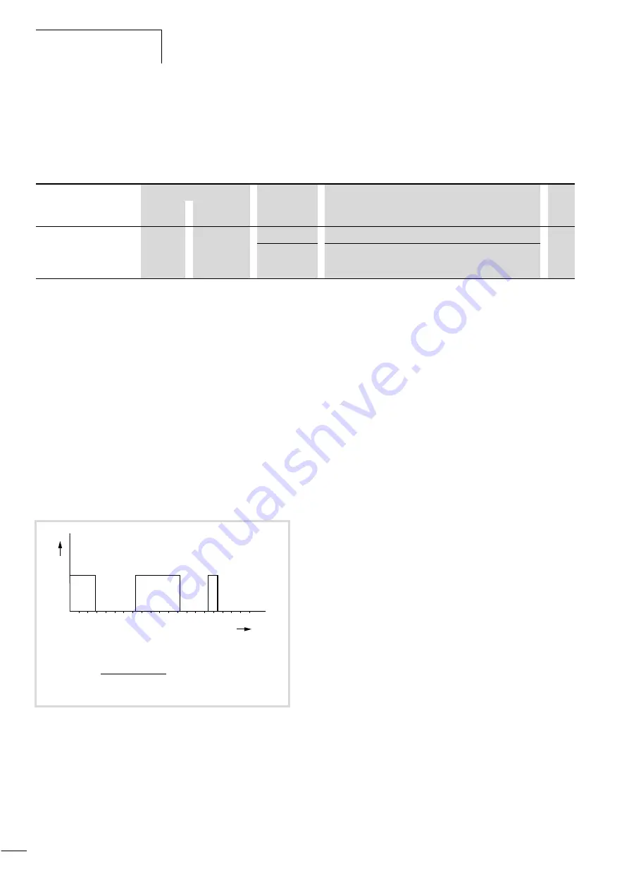
Using an example of three braking operations within 100 seconds,
the illustration below shows the effect of the relative duty factor:
The current relative duty factor T in this example is 44 %.
If, for example, you set PNU b090 to 40 %, a fault message is
issued.
If the braking transistor is operated for a longer period than the
value entered here, fault message E06 is issued.
PNU
Name
Adjustable in RUN mode
Value
Function
WE
Normal
Extended
b088
Motor restart
after removal
of the FRS
signal
–
–
00
0 Hz restart after deactivation of the FRS input
00
01
Synchronization of the motor to the current motor speed
after the waiting time entered under PNU b003.
Figure 169: Example: Braking duration
y: Braking
100
25
50
75
10
0
1
y
t
[s]
T =
14 s + 25 s + 5 s
x
100 % = 44 %
100 s
For Moeller Electric Sales and Support call KMparts.com (866) 595-9616


