2-7
Standard specifications
2Robot arm
2 Robot arm
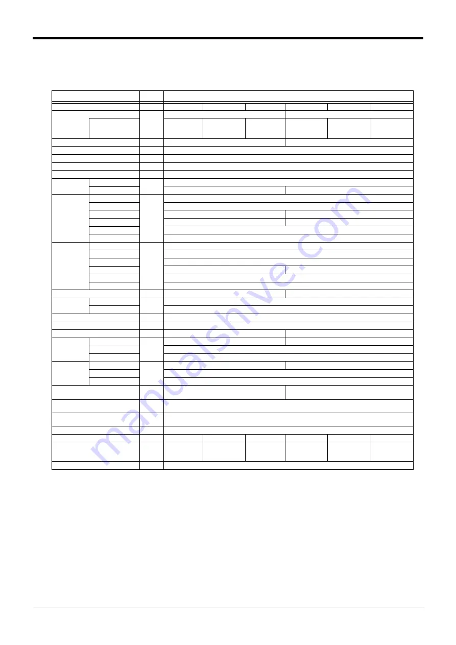
2.1 Standard specifications
Table 2-1 : Standard specifications of robot
Item
Unit
Specifications
Type
RV-3SQ
RV-3SQC
RV-3Q-SM
RV-3SQJ
RV-3SQJC
RV-3SQJ-SM
Type of robot
6-axis
5-axis
Environment
Standard
(oil mist)
Clean
With the con
-
troller protec
-
tion box
Standard
(oil mist)
Clean
With the con
-
troller protec
-
tion box
Degree of freedom
6
5
Installation posture
On floor, hanging,(against wall
Note1)
)
Note1) When used by mounting on the wall, a special specification that limits the operating range of the J1 axis will be used.
Please give an order separately.
Structure
Vertical, multiple-joint type
Drive system
AC servo motor (J1 to J3:and J5: with brake)
Position detection method
Absolute encoder
Arm length Upper arm
mm
245
Fore arm
270
300
Operating
range
Waist (J1)
Note1)
Degree
340 (-170 to +170)
Shoulder (J2)
225 (-90 to +135)
Elbow (J3)
191 (-20 to +171)
237 (-100 to +137)
Wrist twist (J4)
320 (-160 to +160)
-
Wrist pitch (J5)
240 (-120 to +120)
Wrist roll (J6)
720 (-360 to +360)
Speed of
motion
Waist (J1)
Degree/
s
250
Shoulder (J2)
187
Elbow (J3)
250
Wrist twist (J4)
412
-
Wrist pitch (J5)
412
Wrist roll (J6)
660
Maximum resultant velocity
Note2)
Note2) This is the value on the mechanical interface surface when all axes are combined.
mm/sec
5,500
5,300
Load
Maximum
Note3)
Note3) The maximum load capacity is the mass with the mechanical interface posture facing down word at the ±10°limit.
kg
(N)
3.5 (34.3)
Rating
3 (29.4)
Pose repeatability
Note4)
Note4) The pose repeatability details are given in
Page 10, "2.2.1 Pose repeatability"
mm
±0.02
Ambient temperature
℃
0 to 40
Mass
kg
37
33
Allowable
moment load
Wrist twist (J4)
N ・ m
5.83
-
Wrist pitch (J5)
5.83
Wrist roll (J6)
3.9
Allowable
inertia
Wrist twist (J4)
kg ・ m
2
0.137
-
Wrist pitch (J5)
0.137
Wrist roll (J6)
0.047
Note5)
Note5) When the optimum acceleration/deceleration mode is in effect, up to twice the specification value indicated here can
be set.
Arm reachable radius front p-axis
center point
mm
642
641
Tool wiring
Note6)
Note6) The pneumatic hand interface (option) is required when the tool (hand) output is used.
Hand input 8 point, hand output 8 point, eight spare wires
(AWG#24(0.2mm
2
) with shielded)
Tool pneumatic pipes
Primary side: Φ6×2 (Base to fore arm section)
Secondary side: Φ4 ×8 (Optional)
Supply pressure
MPa
0.5±10%
Protection specification
Note7)
Note7) The protection specification details are given in
Page 13, "2.2.5 Protection specifications"
IP65 (all axes)
-
IP65 (all axes)
IP65 (all axes)
-
IP65 (all axes)
Degree of cleanliness
Note8)
Note8) The clean specification details are given in
Page 15, "2.2.6 Clean specifications"
. A down flow(0.3m/s or more) in the
clean room is the necessary conditions for the cleanliness.
-
10(0.3μm)
Internal suction
requirement
-
-
10(0.3μm)
Internal suction
requirement
-
Painting color
Light gray (Equivalent to Munsell: 0.08GY7.64/0.81)
Summary of Contents for MELFA CR1QA-700
Page 2: ......
Page 118: ......
Page 119: ......
Page 120: ......
Page 121: ......
Page 122: ......
Page 123: ......
Page 124: ......
Page 125: ......
Page 126: ......
Page 127: ......
Page 128: ......
Page 129: ......
Page 130: ......
Page 131: ......
Page 132: ......
Page 133: ......
Page 134: ......
Page 135: ......
Page 136: ......
Page 137: ......
Page 138: ......
Page 139: ......
Page 140: ......
Page 141: ......
Page 142: ......
Page 143: ......
Page 144: ......
Page 145: ......


