4
FUNCTIONS
4
- 2
4.2 Specifications on Cyclic Transmission Processing
4.2.1 Cyclic transmission processing
4.2
Specifications on Cyclic Transmission Processing
This section explains the cyclic transmission processing using the CC-Link IE Controller
Network board in the CC-Link IE Controller Network.
4.2.1
Cyclic transmission processing
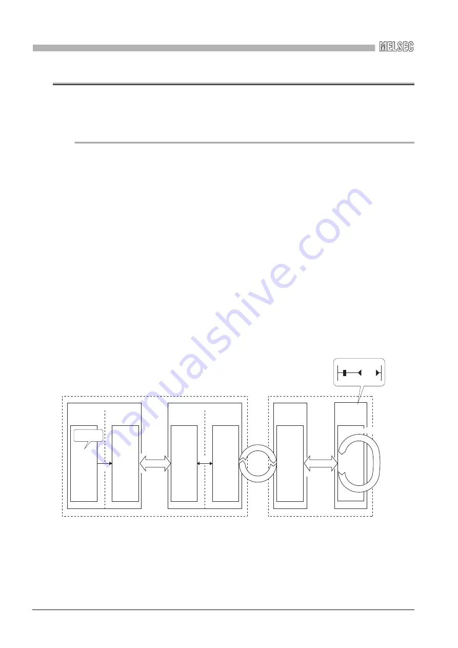
(1) Cyclic transmission processing
Cyclic transmission is performed using the LB/LW/LX/LY devices of the CC-Link IE
Controller Network board and the CC-Link IE Controller Network module.
The steps shown below are for the case of the link relay (B) on the personal computer
side.
1) B0 on the sending side (personal computer) turns on.
2) By a link refresh, the B0 information is stored in the refresh data storage area
(LB) of the CC-Link IE Controller Network board.
3) The B0 information in the refresh data storage area (LB) is stored in the link
data storage area (LB).
4) By a link scan, the B0 information in the link data storage area (LB) is stored in
a link device (LB) of the CC-Link IE Controller Network module on the
receiving side.
5) By a link refresh, the B0 information is stored in a device (B) of the CPU
module.
6) B0 of the receiving side CPU module turns on.
*1: If the CC-Link IE Controller Network board is a control station, configure settings on the "Network
range assignment" screen of the CC IE Control utility.
*2: Configure settings of refresh ranges on the “Refresh parameter setting” screen of the CC IE
Control utility.
LB
LB
B
LB
END
Sending side (personal computer)
Receiving side (programmable controller)
Refresh
data storage
area
Link
refresh
CC-Link IE
Controller Network
driver buffer
User
program
Link data
storage
area *1
Link device
Device
CPU module
CC-Link IE
Controller Network
module
1) B0 turns ON.
2)
3)
4)
Write
Link
refresh
CC-Link IE Controller Network board
Personal computer
Link scan
5)
Sequence scan
B0
6)
Y10
*2


