


6 - 2
6. TROUBLESHOOTING
6.2 Converter unit
6.2.1 Alarms and warning list
When a fault occurs during operation, the corresponding alarm or warning is displayed. If any alarm or
warning has occurred, refer to Section 6.2.2 ro 6.2.3 and take the approporiate action.
Switch power off, then on to deactivate the alarm. The alarms marked " " in the Alarm Deactivation
column of the table can be deactivated by pressing the "RES" key of the servo amplifier side parameter
unit or switching on the reset signal (RES).
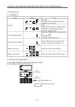
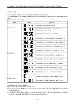
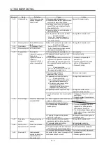
Indication
Function Name
Alarm Deactiviation
A.10
Under voltage
A.12
Memory alarm 1
A.13
Clock alarm
A.15
Memory alarm 2
A.30
Regenerative alarm
A.33
Over voltage
A.37
Parameter alarm
A.45
Main circuit device
overheat
A.50
Over load 1
A.51
Over load 2
Al
ar
m
8888
Watchdog
A.E0
Excessive regenerative
load warning
A.E1
Over load warning
War
ning
A.E9
Undervoltage
warning
6.2.2 Remedies for alarms
CAUTION
•
When any alarm has occurred, eliminate its cause, ensure safety, then reset the
alarm, and restart operation. Otherwise, injury may occur.
POINT
• When any of the following alarms has occurred, always remove its cause
and allow about 30 minutes for cooling before resuming operation. If
operation is resumed by switching control circuit power off, then on to
reset the alarm, the converter unit and regenerative brake option may
become faulty.
• Regenerative alarm (A.30)
• Overload 1 (A.50)
• Overload 2 (A.51)
• The alarms can be deactivated by switching power off, then on, by
pressing the "RES" key of the parameter unit or by turning on the reset
signal (RES).
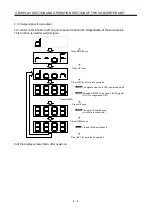
When an alarm occurs, the trouble (ALM) signal switches off and the display section shows the alarm
number.
Remove the cause of the alarm in accordance with this section.
Summary of Contents for Melservo-H Series
Page 11: ... 4 MEMO ...
Page 23: ...1 12 1 FUNCTIONS AND CONFIGURATION MEMO ...
Page 41: ...3 16 3 SIGNALS AND WIRING MEMO ...
Page 49: ...4 8 4 DISPLAY SECTION AND OPERATION SECTION OF THE CONVERTER UNIT MEMO ...
Page 61: ...7 6 7 OUTLINE DIMENSIONAL DRAWINGS MEMO ...
Page 81: ...9 16 9 OPTIONS AND AUXILIARY EQUIPMENT MEMO ...
Page 91: ...App 10 APPENDIX MEMO ...


