


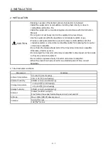


1 - 9
1. FUNCTIONS AND CONFIGURATION
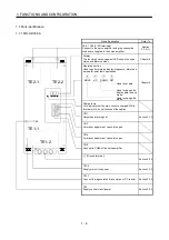
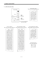
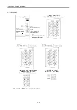
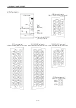
1.7.4 MR-H ACN
CN5
CS1
CN1
CN4
CN3
TE2-2
TE1
TE2-1
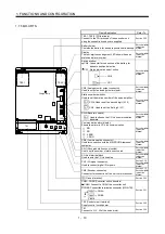
a
Battery holder
Contains the battery for absolute position data backup.
Display
The four-digit, seven-segment LED shows the servo
status and alarm number.
Switch window
x
CN5 : Connector for connection of the battery for
absolute position detection
x
CS1 : Status indication select switch
CN3 (Analog monitor output connector)
Used to output an analog monitor signal.
CN12 (MR-H-D01 option card)
Used to input an auxiliary pulse train when the
MR-H-D01 option card is loaded.
CN4 (Communication connector)
Used for connection with the MR-PRU01A/personal
computer.
CN11 (MR-H-D01 option card)
Used to connect extra digital I/O signals when the
MR-H-D01 option card is loaded.
CN1 (I/O signal connector)
CN2 (Encoder connector)
Connector for connection of the servo motor encoder.
Section 3.2.2
(Ground terminal)
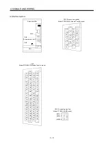
CN5A
CN5B
Fro
n
t
View a
TE3 (Control circuit terminal)
Supply control circuit power.
TE1
Connect to U, V, W of the servo motor.
Refer To
Name/Application
Connect to the PN terminals of the converter unit
using the connection conductors supplied.
TE2-1, TE2-2 (PN terminals)
CN5A, CN5B (Converter unit connectors)
CN5A: Connect to CN5 of the converter unit.
CN5B: Connect the termination connector (MR-A-TM).
Section 3.2.1
Section 3.2.2
Section 3.2.2
Section 3.2.2
Manual
Instruction
Servo Amplifier
Section 9.1.5
Manual
Instruction
Servo Amplifier
Manual
Instruction
Servo Amplifier
Section 9.1.5
Manual
Instruction
Servo Amplifier
Manual
Instruction
Servo Amplifier
Manual
Instruction
Servo Amplifier
Manual
Instruction
Servo Amplifier
Section 3.1.4
Manual
Instruction
Servo Amplifier
Section 3.1.4
Manual
Instruction
Servo Amplifier
Charge lamp
Used to connect digital I/O signals.
Summary of Contents for Melservo-H Series
Page 11: ... 4 MEMO ...
Page 23: ...1 12 1 FUNCTIONS AND CONFIGURATION MEMO ...
Page 41: ...3 16 3 SIGNALS AND WIRING MEMO ...
Page 49: ...4 8 4 DISPLAY SECTION AND OPERATION SECTION OF THE CONVERTER UNIT MEMO ...
Page 61: ...7 6 7 OUTLINE DIMENSIONAL DRAWINGS MEMO ...
Page 81: ...9 16 9 OPTIONS AND AUXILIARY EQUIPMENT MEMO ...
Page 91: ...App 10 APPENDIX MEMO ...


