


3 - 11
3. SIGNALS AND WIRING
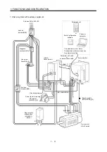
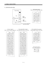
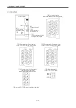
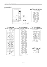
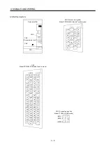
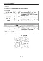
3.2.1 Connection example
48
VDD
22
VIN
20
ALM
RA2
RA3
Fan
EMG
OFF
ON
MC
SK
Servo
RA1
Convert
MC
Fan
G3
G4
G3
G4
G3
G4
P1
P2
(Note2)
P C
L11
L21
OHS2
P C
P C
P C
DC reactor
(Option)
13
12
COM
VDD
8
ALM
3
SE
5
SG
RA3
RA2
RA1
24VDC
power
supply
OHS1
BW
BV
BU
SM
W
V
U
W
V
U
Servo motor
HA-LFseries
MR-A-TM
termination
connector
(Option)
3-phase
200 to
230VAC
50/60Hz
CN5
CN5
P
P
CN5
CN2
L2
L1
L11
L3
L21
MC
NFB
Converter
unit
Servo
amplifier
CN
N
N
P
N
R S
CN1
P
N
External
dynamic
brake
(Note3)
(Note4)
R S
R S
(Note1)
Regenerative
brake option
MR-J2HBUS
M cable
Fan
Fan
Motor thermal relay
Operation-ready
Servo
motor
thermal
relay
Encoder
MR-HSCBL
M cable
(Note1)
Regenerative
brake option
(Note1)
Regenerative
brake option
48
Note: 1. For the MR-RB139. For the MR-RB137, three units are used as one set (permissible wattage:
3900W).
2. When using the DC reactor, disconnect the short bar across P1-P2.
3. When using the external dynamic, Refer to Section 9.1.2.
4. Not provided for the MR-H BN.
Summary of Contents for Melservo-H Series
Page 11: ... 4 MEMO ...
Page 23: ...1 12 1 FUNCTIONS AND CONFIGURATION MEMO ...
Page 41: ...3 16 3 SIGNALS AND WIRING MEMO ...
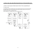
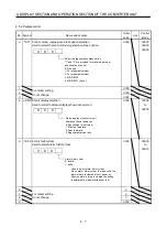
Page 49: ...4 8 4 DISPLAY SECTION AND OPERATION SECTION OF THE CONVERTER UNIT MEMO ...
Page 61: ...7 6 7 OUTLINE DIMENSIONAL DRAWINGS MEMO ...
Page 81: ...9 16 9 OPTIONS AND AUXILIARY EQUIPMENT MEMO ...
Page 91: ...App 10 APPENDIX MEMO ...


