


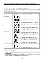


3 - 12
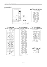
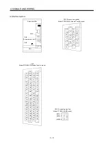
3. SIGNALS AND WIRING
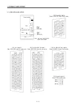
3.2.2 Terminal
Refer to Section 7.2 for the terminal block arrangement and signal layout.
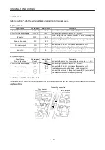
(1) Converter unit
Signal Name
Abbreviation
Terminal Block
Description
Main circuit power supply
L1•L2•L3
TE1-2
Connect three-phase 200 to 230VAC, 50/60Hz to L1, L2, L3.
Control circuit power supply
L11•L21
TE3
Connect single-phase 200 to 230VAC, 50/60Hz.
DC reactor
P1•P2
TE1-1
When using the DC reactor, connect it after removing the
connection plate across P1-P2.
Regenerative brake
P•C
TE1-1
Connect to the P and C terminals of the regenerative brake
option.
PN power output
P•N
TE2-1
TE2-2
Connect to the P and N terminals of the converter unit.
Use the accessory connection bars to make connection.
Grounding
PE
Connect this terminal to the protective earth (PE) terminals of
the servo motor and control box for grounding
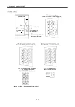
(2) Servo amplifier
Signal Name
Abbreviation
Terminal Block
Description
Servo motor output
U•V•W
TE1A
Connect to the servo motor power supply terminals (U, V, W).
Control circuit power supply
L11•L21
Connect single-phase 200 to 230VAC, 50/60Hz.
PN power supply
P•N
TE2-1
TE2-2
Connect to the P and N terminals of the converter unit.
Use the accessory connection bars to make connection.
Grounding
PE
Connect this terminal to the protective earth (PE) terminals of
the servo motor and control box for grounding
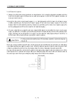
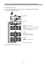
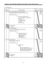
3.2.3 How to use the connection bars
Connect P and N of the servo amplifier and P and N of the converter unit using the connection conductors
as shown below.
Converter unit
Servo amplifier
Connection conductors
Summary of Contents for Melservo-H Series
Page 11: ... 4 MEMO ...
Page 23: ...1 12 1 FUNCTIONS AND CONFIGURATION MEMO ...
Page 41: ...3 16 3 SIGNALS AND WIRING MEMO ...
Page 49: ...4 8 4 DISPLAY SECTION AND OPERATION SECTION OF THE CONVERTER UNIT MEMO ...
Page 61: ...7 6 7 OUTLINE DIMENSIONAL DRAWINGS MEMO ...
Page 81: ...9 16 9 OPTIONS AND AUXILIARY EQUIPMENT MEMO ...
Page 91: ...App 10 APPENDIX MEMO ...


