


1 - 11
1. FUNCTIONS AND CONFIGURATION
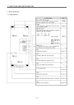
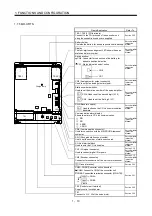
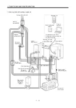
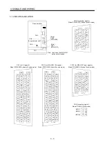
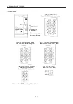
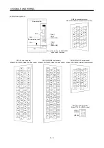
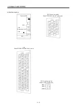
1.8 Servo system with auxiliary equipment
Converter unit
Servo amplifier
3-phase, 200 to 230VAC
No-fuse
breaker(NFB)
Magnetic
contactor(MC)
Line noise
filter(FR-BLF)
R S T
Servo motor
HA-LF series
R1
S1
C
P
BU BV BW
U
P
N
L1
L2
L3
P1
W
P
N
V
W
E
V
CN1
P2
P C
CN1
CN5
L21
L11
U
CN5A
L21
L11
CN2
Encoder cable
(Note3)
Parameter unit cable
or
communication cable
Servo Configuration
software
Personal
computer
Parameter unit
or
CN4
(MR-HSCBL M)
The parameter unit or Servo
Configuration software is required
for parameter setting.
No-fuse
breaker(NFB)
(Note 1)
(MR-J2HBUS M)
(Control signal)
Regenerative
brake option
(Note 2)
Power factor improving
DC reactor
(MR-DCL K)
(MR-RB )
Summary of Contents for Melservo-H Series
Page 11: ... 4 MEMO ...
Page 23: ...1 12 1 FUNCTIONS AND CONFIGURATION MEMO ...
Page 41: ...3 16 3 SIGNALS AND WIRING MEMO ...
Page 49: ...4 8 4 DISPLAY SECTION AND OPERATION SECTION OF THE CONVERTER UNIT MEMO ...
Page 61: ...7 6 7 OUTLINE DIMENSIONAL DRAWINGS MEMO ...
Page 81: ...9 16 9 OPTIONS AND AUXILIARY EQUIPMENT MEMO ...
Page 91: ...App 10 APPENDIX MEMO ...


