


2 - 2
2. INSTALLATION
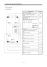
2.2 Installation direction and clearances
CAUTION
• Install the equipment in the specified direction. Not doing so can cause a failure.
• Leave the specified clearances between the converter unit/servo amplifier and the
control box inside walls or other equipment. Not doing so can cause a failure.
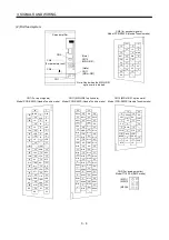
(1) Installation of one servo amplifier
Servo Amplifier
50mm
(1.969in)
or more
100mm
(3.937in)
or more
12
0
m
m
(4.724i
n
)
o
r more
Front view
Top
Bottom
Converter unit
50mm
(1.969in)
or more
10
0
m
m
(3.937i
n
)
o
r more
Side view
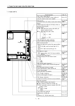
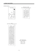
(2) Mounting dimensional diagram
Converter
unit
Servo amplifier
Exclusive
connection conductor
8-M10 screw
110
(4.33)
200
(4.66)
20
W2
W1
48
0(1
8
.9
)
50
0(1
9
.69)
10
(0.
3
9
)
10
(0
.39)
Servo Amplifier Model
W1
W2
450
(17.717)
360
(14.173)
[Unit: mm]
([Unit: in])
MR-H30K
45
(1.77)
45
(1.77)
45
(1.77)
45
(1.77)
Dimension
(0.47)
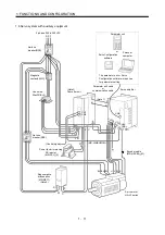
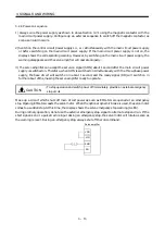
(3) Others
When using heat generating equipment such as the regenerative brake option, install them with full
consideration of heat generation so that the Converter unit and servo amplifier is not affected.
Install the Converter unit and servo amplifier on a perpendicular wall in the correct vertical direction.
Summary of Contents for Melservo-H Series
Page 11: ... 4 MEMO ...
Page 23: ...1 12 1 FUNCTIONS AND CONFIGURATION MEMO ...
Page 41: ...3 16 3 SIGNALS AND WIRING MEMO ...
Page 49: ...4 8 4 DISPLAY SECTION AND OPERATION SECTION OF THE CONVERTER UNIT MEMO ...
Page 61: ...7 6 7 OUTLINE DIMENSIONAL DRAWINGS MEMO ...
Page 81: ...9 16 9 OPTIONS AND AUXILIARY EQUIPMENT MEMO ...
Page 91: ...App 10 APPENDIX MEMO ...


