


4 SERVO PROGRAMS FOR POSITIONING CONTROL
4.4 Setting Method for Positioning Data
249
4
Inputting of positioning data
In indirect setting by word devices, the word device data is inputted when the servo program is executed using the Motion
CPU.
It must be executed the start request of the servo program after data is set in the device used for indirect setting at the
positioning control.
The procedures by start method for setting data to devices and cautions are shown below.
• Take an interlock condition by using a "[St.1040] Start accept flag (R: n/Q: M2001+n)" not to
change the device data for indirect setting until the specified axis has accepted the start command. If the
data is changed before the start command is accepted, positioning may not be controlled in a normal value.
• For data that uses 2 words, always set a device with an even number.
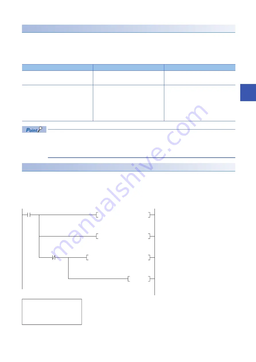
Program example that uses the CPU buffer memory
Program example to control by the data transmitted from the PLC CPU to Motion CPU is shown below.
■
Program
Program that starts the servo program (positioning) by the MP.SVST instruction after the data is written to the CPU buffer
memory (U3E0\G10000 to U3E0\G10003) from the PLC CPU (CPU No.1).
Start method
Setting method
Notes
Start by the servo program
Set data in indirect setting devices.
Start the servo program.
Do not change the indirect setting device before
the "positioning start complete signal" of the
starting axis turns on.
Set the loop (FOR - NEXT) point data for
CPSTART instruction indirectly
Set initial command data in the indirect setting
device.
Start using the servo program.
Read the value of "data set pointer for continuous
trajectory control" of the start axis, and update the
data input by Motion CPU.
Refer to the axis monitor devices for details.
(
Page 97 [Md.1011] Data set pointer for
continuous trajectory control (R: 48n/Q:
D15+20n))
M0
Instruction
execution
command
DMOVP K10000 U3E0\G10000
Servo program
K10 position
command
DMOVP K10000 U3E0\G10002
Servo program
K10 speed
command
MP.SVST H3E1 "J1" K10 M100 D100
RST M0
Instruction
execution
command
U3E1
\G516.0
Start accept
flag of CPU
No.2 (Axis 1)
Sequence program (PLC CPU side)
Servo program (Motion CPU side)
[K 10: Real]
1 INC-1
Axis 1, U3E0\G10000
μ
m
Speed U3E0\G10002 mm/min
Summary of Contents for MELSEC iQ-R16MTCPU
Page 2: ......
Page 477: ...APPENDICES Appendix 1 Processing Times of the Motion CPU 475 A MEMO ...
Page 481: ......


