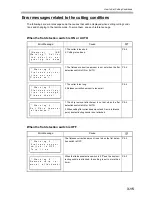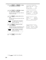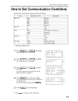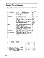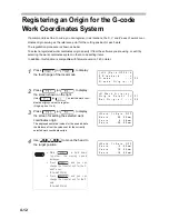
How to Set the Mode Switch
4-7
How to Set the Mode Switch
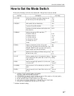
There are the following set items in the mode switch. Change the set value as needed.
“*” indicates the default setting.
Set Item
Description
Set Value
AUTO VIEW
Sets the time between completion of engraving and
the head moving out of the engraving area.
*OFF
1 sec
3 sec
FLATNESS
Not to perform the auto flat detection
*OFF
To perform the auto flat detection
ON
To perform the auto flat detection and the flatness fol-
low-up function
AUTO
COMMAND
Sets the command and GDP (resolution).
*1*2
IIc-25:MGL-IIc325 μm
IIc-10:MGL-IIc310 μm
Ic1-50:MGL-Ic150 μm
Ic1-100:MGL-IC1100 μm
Ic1-10:MGL-IC110 μm
G-code
*1. If changed, all the coordinate systems are initialized.
Also all the receive buffer contents are cleared.
*2. If COMMAND set is changed, recheck the response value to OH command and the origin position.
IIc-25
*IIc-10
c-50
c-100
c-10
G-code
*3*4*5
*3. G-code is compatible with firmware version 1.40 or later.
*4. Set the resolution using a G-code in another menu. (
P.4-10)
*5. If a G-code is selected, auto flat detection or flatness follow-up is not performed.
SPINDLE
Enables or disables the rotation of the spindle.
If OFF is set, the spindle will not rotate even if the
SPINDLE ON/OFF switch is pressed or the spindle
on/off command is sent from the computer.
*ON
OFF
UNIT
Sets the unit for indicating coordinates during moving
the head to mm or inch.
*mm
inch
OH UNIT
Sets the response value to OH command to the max-
imum effective area value (initial value) or the LL/UR
value (set value).
*Maximum
Setting
ORIGIN
Sets the command origin position (0, 0) to the center
or the lower left.
*1
Center
*Low-Left
Z SIGN(ZM)
Sets the direction of Z coordinate axis in ZM com-
mand.
*P(+)
M(-)
PAUSE
*6
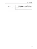
*6. This function is compatible with firmware version 1.40 or later.
When you pause, you can select the to intact or up
the tool.
*Tool_up
Not_up
Summary of Contents for ME-300STII
Page 12: ...12 Machine Specification 6 10 Interface Specification 6 11 Supported G code List 6 12...
Page 26: ...2 2 Operation Panel The names and functions of the operation panel components are as follows...
Page 68: ...4 14...
Page 69: ...5 1 CHAPTER 5 ERRORS AND SOLUTIONS...
Page 76: ...5 8...
Page 77: ...6 1 CHAPTER 6 APPENDIX...
Page 89: ......

