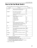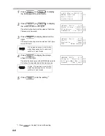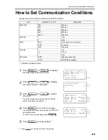
3-12
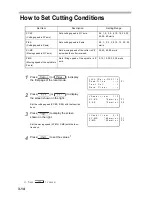
How to Set Cutting Depth / Lifting
Amount in Z Axis
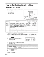
Specify cutting depth and lifting amount of the cutter in
terms of Z axis.
A = Cutting depth
B = Lifting amount
1
Press
to display the screen
shown as the right.
2
Adjust the cutting depth with the function keys.
Refer to the table below.
3
Press
to set.
*1
Set Value
Set Item
Description
With the chip
removal attach-
ment
Without the chip
removal attach-
ment
Depth
Set the cutting depth from the Z axis reference point.
0.0 to 4.0 mm
*1
*1. The settable cutting depth relates to the flatness correction amount.
See "How to Set Flatness Correction Amount" (P.3-10).
0.0 to 60 mm
Up Hight
Set the lifting amount from the Z axis reference point.
*2
*2. When the flat detection switch is ON or AUTO, enter a distance between the tip of the chip removal attach-
ment and the work. When the flat detection switch is off, enter a distance between the tip of the cutter and
the work.
0.0 to 60 mm
0.0 to 60 mm
Auto ADJ.
Set this value when the flat detection is ON or AUTO,
because the cutter may cut into the work even when the cut-
ting depth is set to 0.
-0.5 to 0.5 mm
-0.5 to 0.5 mm
Set this value when the flat detection is off and auto setting
of Z axis reference point is on, because the detected Z axis
reference point does not fit to the surface of the work.
Adjust this value when setting the flatness correction amount
to cut more precisely.
Key operation
Set value
Press
(or
).
Changes the value by 0.01 mm.
Press and hold down the
(or
). Change the increase or decrease amount depending on
the time you press and hold
*1. Press
to cancel.
Z axis reference
point
Cutting depth
Work
Lifting amount
< Z
a x i s >
[ mm ]
D e p t h
* 0 . 3 0 >
A u t o
A D J .
* 0 . 3 0 >
U p
H i g h t
* 0 . 3 0 >
F 1
F 2
F 3
Summary of Contents for ME-300STII
Page 12: ...12 Machine Specification 6 10 Interface Specification 6 11 Supported G code List 6 12...
Page 26: ...2 2 Operation Panel The names and functions of the operation panel components are as follows...
Page 68: ...4 14...
Page 69: ...5 1 CHAPTER 5 ERRORS AND SOLUTIONS...
Page 76: ...5 8...
Page 77: ...6 1 CHAPTER 6 APPENDIX...
Page 89: ......

