Chapter 6 Trigger System
89
When we set a specific trigger condition for a specific signal, especially when the time interval for satisfying the
trigger condition is long, we need to set the trigger mode to “
Normal
” so as to prevent the oscilloscope from
automatic forced trigger.
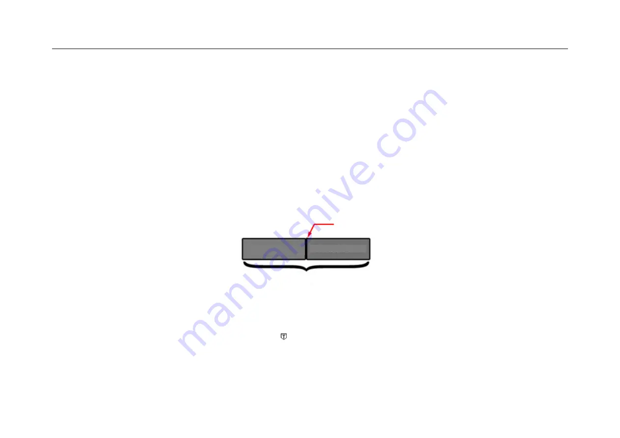
Figure 6-6 shows a conceptual demonstration of the acquisition memory. In order to understand the trigger event,
the acquisition memory can be divided into pre-trigger and post-trigger buffers. The position of the trigger event in
the acquisition memory is defined by the time reference point and trigger position (horizontal delay) settings.
Figure 6-6 Conceptual Demonstration of Acquisition Memory
All events displayed to the left of the trigger point occur before trigger. These events are called pre-trigger
messages that show events before the trigger point. All events to the right of the trigger point is called post-trigger
Trigger Event
Acquisition Memory
Pre-trigger Buffer
Post-trigger Buffer
Summary of Contents for Smart Series
Page 1: ......
Page 2: ...Version Info Version Date Remarks V2 0 2019 10 ...
Page 25: ...Chapter 2 Quick Start Guide of Oscilloscope 11 2 3 Side Panel Figure 2 2 Side Panel ...
Page 30: ...16 Figure 2 5 Oscilloscope Interface Display ...
Page 51: ...Chapter 3 Operate the Oscilloscope with Buttons 37 Figure 3 1 Button Areas ...
Page 61: ...Chapter 4 Horizontal System 47 Figure 4 1 Horizontal system ...
Page 82: ...68 Figure 5 4 Channel Open Close and Switching ...
Page 88: ...74 Figure 5 7 DC Coupling Figure 5 8 AC Coupling ...
Page 126: ...112 Figure 6 21 Trigger Level Adjustment Trigger pulse width time can be set as 8ns 10s ...
Page 150: ...136 Figure 7 2 Pull up Menu Figure 7 3 All Measurements ...
Page 161: ...Chapter 7 Analysis System 147 Figure 7 10 Cursor Measurement Description ...
Page 176: ...162 Figure 8 5 Delete Reference Files CSV files CSV file structure ...
Page 190: ...176 Figure 9 4 Spectrum Amplitude as V Hz Adjust FFT waveforms Waveform position ...
Page 324: ...310 Figure 14 6 Android APP Figure 14 7 Successful Connection of Android APP ...


