


Chapter 14 Remote Control
197
the entered IP address.
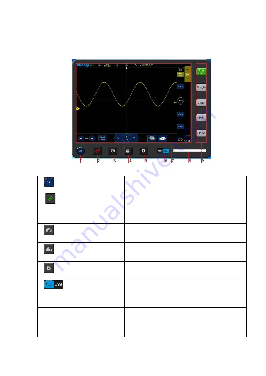
14.1.3 Main Interface Introduction
Figure 14-2 Host Computer Interface
1.
Host computer on/off button
Click to exit the host computer software
2
Oscilloscope connection status
button
The button has two states:
Green: Connect to selected oscilloscope when clicked
Red: Disconnect from oscilloscope when clicked
3.
Quick camera button
Click to take photo quickly. Pictures are stored in the local
directory C:\Users\Public\Pictures
4.
Video record button
Click to open or close video record function. Videos are stored
in local directory C:\Users\Public\Videos
5.
Host computer storage button
Set photo taking and video recording storage locations
6.
Select oscilloscope connection
mode
USB and WIFI connections are available
Note: WIFI connection must ensure that oscilloscope and computer
are in the same network
7. Host computer display area
Synchronous display with oscilloscope
8. Oscilloscope information display
Display oscilloscope model, connection mode, SN, IP and
other information, select the oscilloscope to be connected
Summary of Contents for ATO1000 Series
Page 1: ......
Page 2: ...Version Info Version Date Remarks V1 0 2020 06 ...
Page 52: ...Chapter 3 Automotive Test 49 Figure 3 30 Electronic fuel pump test ...
Page 71: ...68 Figure 3 49 K line test ...
Page 79: ...76 Figure 3 57 Mazda 6 Cylinder internal pressure measurement ...


