


Chapter 13 Serial Bus Trigger and Decode (Optional)
181
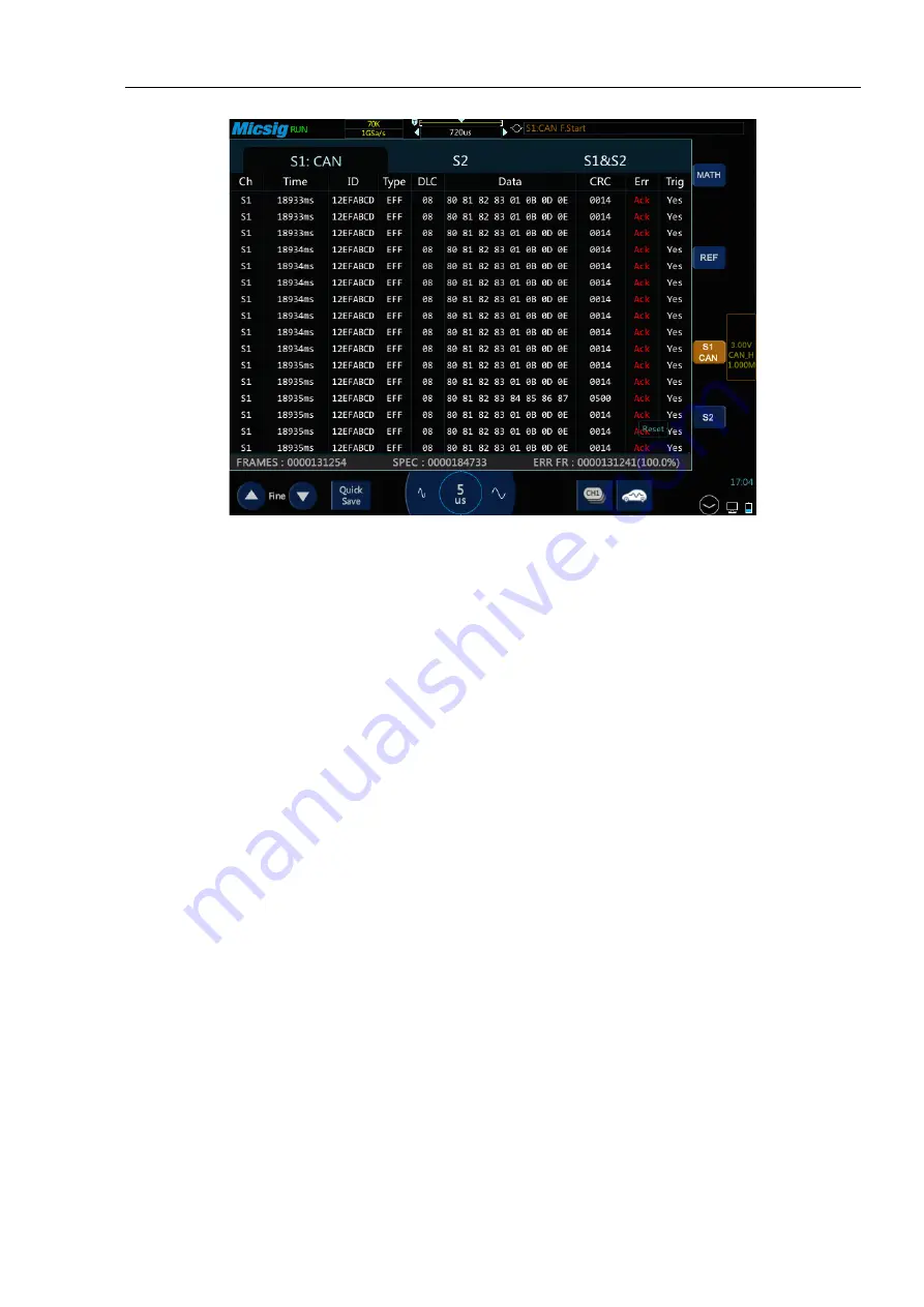
Figure 13-17 CAN Text Interface
CAN text interface description, as shown in Figure 13-17:
(1) “Ch”: bus channel.
(2) “Time”: Time intervals between the last frames to current frames.
(3) “ID”: CAN frame ID value displayed in hexadecimal, maximum 29 bits.
(4) “Type”: Frame type, “SFF” standard data frame, “SRF” standard remote frame, “EFF” extended data
frame, “ERF” extended remote frame.
(5) “DLC”: Number of data bytes sent by this frame. This value can be ignored for remote frames.
(6) “Data”: Frame data.
(7) “CRC”: Frame CRC check code.
(8) “Err”: Response error, bit stuffing error, format error, CRC error.
(9) “Trig”: “Yes” means the frame reaches trigger condition.
(10) “Statistics”: counts the number of occurrences of frame type, data length, status, etc., and the
percentage.
13.4
SPI Bus Trigger and Decode
For correctly decoding SPI bus data and making trigger stable, the bus configuration, trigger mode set and trigger
level need to be adjusted.
⚫
Bus configuration
Summary of Contents for ATO1000 Series
Page 1: ......
Page 2: ...Version Info Version Date Remarks V1 0 2020 06 ...
Page 52: ...Chapter 3 Automotive Test 49 Figure 3 30 Electronic fuel pump test ...
Page 71: ...68 Figure 3 49 K line test ...
Page 79: ...76 Figure 3 57 Mazda 6 Cylinder internal pressure measurement ...


