4-14
Workstation 5 Field Service Guide
Remove and Replace the Workstation 5 FRUs
LCD/Touchscreen Procedures
2.
For the remaining steps, refer the lower section of Figure 4-13, on the
previous page.
3.
Note the LCD panel maker. It will be from Sharp or AUO.
4.
Feed each backlight cable through the cut-outs in the LCD Plate, then fit
the LCD/Touchscreen Bracket assembly inside the LCD Plate. Make sure
the clips in each corner of the bracket project through the cut-outs in the
LCD plate.
5.
Place the assembly face down and check the backlight cables to ensure
they are not pinched between the LCD Plate and LCD Panel. Connect each
Backlight cable to the Backlight Inverter Board.
6.
Connect the LCD Data Cable to the LCD Panel.
7.
Place the touchscreen ribbon cable in the guide under the Backlight
Inverter as shown in the lower half of Figure 4-13. Failure to place the
ribbon cable under the Backlight Inverter Board could cause it to come in
contact with high voltage.
o
If the Capacitive Touchscreen option is installed, make sure the
touchscreen ribbon cable passes under the Capacitive Touchscreen
Interface Board, before connecting to J1.
8.
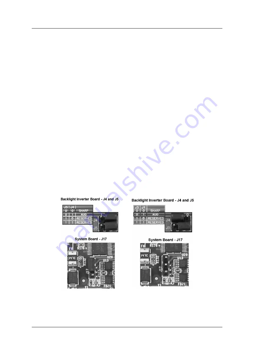
Check the LCD Configuration Jumpers on the Backlight Inverter Board
and System Board. Refer to Figure 4-14 below to set the Backlight Inverter
Board and System Board.
Figure 4-14: LCD Configuration Jumpers
9.
See page 4-27 to reinstall the LCD/Touchscreen Assembly.
Sharp
AUO


