


124
Operation
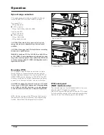
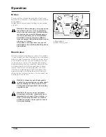
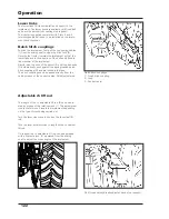
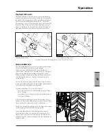
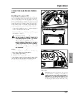
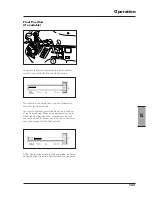
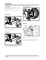
Adjustable top link (3rd point)
The adjustable top link (1) is connected to the tractor
through a bearing with two holes (2). The connection
hole should be selected according to the reaction to the
draft control.
Connection to the top hole gives a lower sensitivity, to
the bottom hole a higher sensitivity to the hitch draft
control.
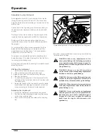
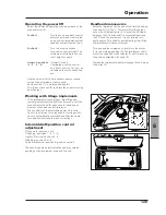
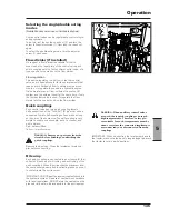
The length of the link is varied so that the angle of the
implement can be regulated in relation to the ground.
During work, the top link should go slightly down
toward the tractor, when the lower links are parallel to
the ground.
For works in draft control mode, remember that it is
better to hitch the implement in the top hole if the
carried load is particularly heavy. This way a greater
uniformity of work is achieved.
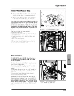
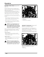
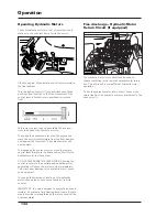
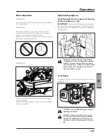
On request, the adjustable top link is available with a
hydraulic device (1) to adjust the length of the link from
the driving place during work.
The top link has two holes for hitching the implement and
adjusting its slant.
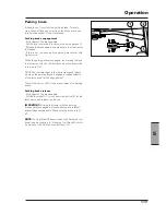
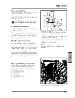
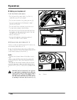
Hitching the implement
1 - Set the lift controls in position control mode..
2 - Allow the three point linkage to descend.
3 - Adjust the top links to have maximum side play.
4 - Back up the tractor.
5 - Connect the coupling bar of the implement to the
ball-ends of the lower links and lock it in place with
the safety pins.
6 - Adjust the length of the top links to give the imple-
ment freedom of sideways movement or lock it in
place according to the type of work required.
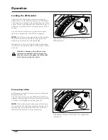
Releasing the implement
1 - Lower the implement completely to the ground.
2 - Shorten the side stabilizers to give maximum play
to the lower hitching links.
3 - Remove the safety pins and release the coupling
bar.
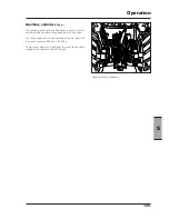
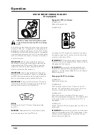
Hydraulic adjustment of top link (3rd point) (on request).
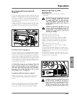
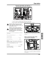
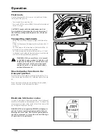
Important recommendations when using and adjusting
the three point linkage.
WARNING: before any adjustments in the
three point linkage, the following operations
are required: engage the first gear, engage the
parking brake, turn the engine off and remove
the ignition key.
WARNING: Always use the lift in position
control mode when transporting implements
hitched to the three point linkage.
WARNING: Always use the lift in position con-
trol mode when an implement is hitched or
unhitched to or from the three point linkage.
WARNING: When the tractor is stopped, always
lower any implements connected to the three
point linkage.
[4.2.c]
WARNING: Never work under an implement
that is kept raised only by the hydraulic hitch,
but always secure it with a suitable support.
Engage the first gear, engage the parking
brake, turn the engine off and remove the
ignition key.
Summary of Contents for X60 Series
Page 39: ...39 Controls Cab 3 Section 3 Controls Cab...
Page 61: ...61 Instruments and Programming 4 Section 4 Instruments and Programming...
Page 90: ...90 Instruments and Programming This page has been left blank intentionally...
Page 91: ...91 Operation 5 Section 5 Operation...
Page 151: ...149 Tyres Wheels Ballasting 6 Section 6 Tyres Wheels Ballasting...
Page 168: ...166 Tyres Wheels Ballasting This page has been left blank intentionally...
Page 169: ...167 Maintenance 7 Section 7 Maintenance...
Page 229: ...Electrical system 227 8 Section 8 Electrical system...
Page 242: ...Electrical system 240 Page left intentionally blankf...
Page 256: ...Technical specifications 254 This page has been left blank intentionally...
Page 262: ...260 Alphabetical index...