background image

109

Operation

5

Electro-hydraulic PTO

The rear power take-off is fully independent from the 
transmission. It is engaged by means of a multi-disc 
oil-cooled hydraulic clutch.

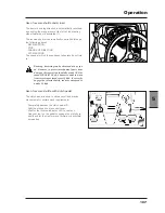
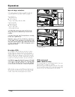
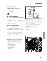
The PTO is engaged by means of the switch (1).

An indicator light on the instrument panel comes on 
when the PTO is engaged.

Use: engagement/disengagement 

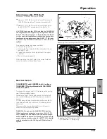
Engage/disengage the front PTO (1) by the ON/OFF 
button switch with engine at idling speed.

Depressed button switch

: disengaged PTO

Released button switch:

  engaged PTO

To engage the PTO, release the switch (1) by pulling up 
the locking collar (2).

Always shift the switch in the OFF disengaged position 
after using the  PTO or before starting the engine.

NOTE: 

The engine can be started only if the PTO 

engagement switch is in the OFF position and the PTO 
engagement lever (3) is in the neutral position.

Engage the PTO at a low RPM speed to protect the clutch 
and driveline.

Select the operating mode and the required speed before 
engaging the PTO.

IMPORTANT: For high-inertia implements (e.g. stone 
crusher, mill etc.) the universal joint for cardan shaft 
is to be used.

WARNING:  When  using  the  PTO  with  the 
tractor  at  a  standstill,  always  make  sure 
that  the  creeper  lever  of  the  gearshift  in 
neutral position and that the parking brake 
is engaged.

WARNING:  High-inertia  implements  do  not 
stop immediately after the independent PTO 
has been disengaged.  Wait for the implement 
to  slow  down  or  stop  completely  before 
performing  any  cleaning  or  adjustment 
operations.

IMPORTANT:

 When using implements that cause shock 

loads, always use a safety coupler between the implement 
and the PTO drive shaft. Before using the implement, check 
the correct operation both of the safety coupler and of the 
implement.

Disengagement 
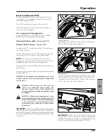
Fully depress the ON/OFF switch (1). The PTO indicator 
light on the instrument panel goes off.

Engagement 
Pull up the locking collar (2) of the ON/OFF button, then 
pull the button (1) to the ON position. Now the button 
will remain on the ON position, while the PTO indicator 
light on the instrument panel lights up.

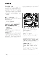
IMPORTANT:

  When  using  implements  with  quickly 

moving  parts  (such  as  mowers,  reapers,  snowplows) 
ALWAYS  fit  an  overrun  device  on  the  implement  drive 
shaft, as a protection against possible PTO faults.

Summary of Contents for X60 Series

Page 1: ...D PROGRAMMING OPERATION TYRES WHEELS BALLASTING REGULAR SERVICE INTERVALS ELECTRICAL SYSTEM TECHNICAL SPECIFICATIONS ALPHABETICAL INDEX 2 3 4 6 7 SECTION 5 1 X60 Series 8 9 X60 20 X60 30 X60 40 X60 50...

Page 2: ...e requirements of the Machinery Directive 2006 42 EC and Directive 2010 52 EC in force in the Euro pean Community For tractors sold or used outside the European Community local laws will prevail Main...

Page 3: ...he tractor 16 Save the environment 16 Safety Tractor maintenance 16 Safety Starting up 17 Working in safety 19 Correct manoeuvres 19 Working in safety 19 Beware of other people 20 Risk of overturning...

Page 4: ...trailer brakes 118 Trailer air brakes 119 Differential lock 120 Two wheel drive 120 Three point hitch 121 Hydraulic hitch with electronic control 126 Auxiliary control valves 131 Front power takeoff i...

Page 5: ...utting the tractor into storage 225 Section 8 Electrical system 227 Batteries 228 Fuses 233 Headlights 236 Trailer power socket 237 3 pin electrical socket 12V 238 Implement cable access 239 Section 9...

Page 6: ...r The vehicle identification number is punched both on the data plate and on the right hand front side of the weight frame 2 Tractor identification data The engine has its own serial number stamped on...

Page 7: ...sulting from the fitment of non approved parts or attachments or unauthorized modification or alteration Introduction INTRODUCTION NOTE This manual is distributed with tractors all over the world The...

Page 8: ...ansferred to the latter If you moved from the area of your original Dealer without any arrangements with the new Dealer the latter will give you assistance for emergencies but will charge normal price...

Page 9: ...rfectly controls and driving technique External controls of hitch and electro hydraulic power take off if equipped must be operated standing on one side outside the tractor and keeping oneself out of...

Page 10: ...ep through your working day DO NOT USE THE MACHINE IF YOU HAVE ANY DOUBTS In reading this section you will note that illustrations have been used to highlight certain situations Each illustration is n...

Page 11: ...le SAFETY FOLLOWING A SAFETY PROGRAM Safe use of the tractor Only qualified and authorized operators are able to use farming tractors in safety To be qualified you must under stand the written instruc...

Page 12: ...DE LUXE CAB WARNING Tractors equipped with De Luxe cab have a protection FOPS against objects and loads that might fall from above in typi cal work conditions but not against objects and loads that mi...

Page 13: ...The tractor is anyway designed to install a 1 kg dust fire extinguisher complying with UNI EN 3 7 2004 standard The fire extinguisher must be mounted in the reserved and indicated position Fig 2 4a F...

Page 14: ...s It must always be kept with the tractor For further copies contact your Dealer Use all available protective devices Keep all protective devices in place and securely fastened Make certain all guards...

Page 15: ...iesel fuel or hydraulic fluid un der pressure can pierce the skin or eyes and cause serious personal injury blindness or death Fluid leaks under pressure may not be visible Use a piece of cardboard or...

Page 16: ...y adjustments or servicing on the electrical system disconnect the battery by operating the mas ter disconnect switch if equipped or disconnecting the cables of the battery See the section concerning...

Page 17: ...levers as a hand hold and NEVER step on foot controls when mounting or dismounting NEVER try to go on or off the moving tractor If the tractor must be lifted for servicing take it to a sui tably equi...

Page 18: ...river s seat DO NOT attempt to start the engine by shorting across the terminals of the starter motor If the starter circuit is bypassed to neutral the tractor could start with an en gaged gear with d...

Page 19: ...lement or equipment you are going to use does NOT exceed the load capacity of your tractor Check that the coupling PTO shaft implement is correct see the Technical Specifications section for mass data...

Page 20: ...everything is operating regularly After starting turn the steering right and left to check for correct operation Check steering and brake system for operation If differential is locked DO NOT operate...

Page 21: ...ad as low as possible Make wide slow turns at reduced speed DON T let your tractor bounce You may loose steering con trol DON T pull a load too heavy for your tractor It could run away on the down slo...

Page 22: ...but slow down and take a wide turn Always drive straight up or down a slope never across it When travelling up or down a slope keep the heavy end of the tractor and the implement pointed uphill Fig 2...

Page 23: ...overturn which may cause serious injury or death Hitch loads to the drawbar only Use front counterweights to increase tractor stability when towing a heavy load or to counter balance a heavy rear mou...

Page 24: ...ement and attempt to BACK OUT If this is not possible tow it out with another vehicle If you get stuck in a ditch BACK OUT if possible If you must go forward do it slowly and carefully When driving on...

Page 25: ...he operating range of the machine DO NOT use PTO adaptors reducers or extensions as they extend the PTO coupler and universal joint out beyond the protection offered by the PTO shield The top link and...

Page 26: ...4 2 b To use mounted semi mounted or towed equipment and trailers it is required to use exclusively CE marked implements after reading their operation handbooks carefully giving maximum attention to...

Page 27: ...be taken WARNING DO NOT allow any passengers on the tractor or towed equipment Know the route you are going to travel Use the prescribed lights or if required the rotating beacon both in the daytime a...

Page 28: ...system on the tractor STAY OUT of the path of oncoming traffic Drive in your correct lane keeping as near to the curb as possible If traffic builds up behind you pull off the road and let it go by Dri...

Page 29: ...ly during tillage On normal terrain in good operating conditions wheel slip should be between 4 and 10 On loose soil wheel slip can exceed 12 If wheel slip is found to be greater than this amount proc...

Page 30: ...ufficiently in order to avoid damage to the tractor s hydraulic system 8 Towing heavy loads trailers etc When heavy loads are towed the road rules in some countries require a supplementary braking sys...

Page 31: ...kground noise it can only be detected by means of an audiometric test Pulsating noises of great intensity lasting a very short time are highly damaging since the ear is unable to actuate any physiolog...

Page 32: ...belts or pulleys when engine is on Keep guards in place DECAL 3 WARNING Danger of entangle ment Keep hands well clear of fan blades when engine is run ning Keep guards and screens in place DECAL 1 WA...

Page 33: ...and se rious accidents Keep to one side of the tractor when using external lift controls NEVER STAND betwe en tractor and implement you could be hit by the implement DECAL 7 WARNING Very hot surfaces...

Page 34: ...f the tractor when using external lift controls NEVER STAND between tractor and implement you could be hit by the implement DECAL 21 Located near the front hitch if equipped DANGER Beware of hanging l...

Page 35: ...sk goggles suitable to the harmfulness of the actual product used Decal 23 WARNING Use individual protections during work such as overalls heavy duty gloves and safety foo twear Decal 25 WARNING Dange...

Page 36: ...ds covers and guards in place while engine is running Beware hot parts DECAL 1 Warning Very hot sur faces Do not remove any guards to avoid injuries WARNING Keep hands clear of fan and belts while eng...

Page 37: ...ns Contains sulphuric acid Avoid contact with skin eyes or clothing In event of accident flush with water and call a physician immediately Keep out of reach of children DECAL 6 Batteries produce explo...

Page 38: ...t at minimum distance B and will have sufficient overlap at maximum distance DECAL 12 Warning Separation of the PTO drive line might cause seri ous accidents Adjust the connections carefully CAUTION R...

Page 39: ...39 Controls Cab 3 Section 3 Controls Cab...

Page 40: ...OR ACCESS 4 1 e Cab Door Lock The ignition key is also used to lock or unlock the cab door from the outside Cab emergency exit 4 1 d The rear window of the cab may be used as an emer gency exit Access...

Page 41: ...e and shifting the gear to neutral Machines with hydraulic reverse shuttle are equipped with a further restraint that acts whenever the operator gets off his her seat without turning off the engine wi...

Page 42: ...perator s weight is displayed in the indicator WARNING To avoid injuries the operator s weight setting should be checked and ad justed to the operator before starting the tractor 1 4 3 2 1 FORE AFT AD...

Page 43: ...UMBAR ADJUSTMENT CONTROL Turn the adjust ment knob as required 8 SWIVEL ADJUSTMENT CONTROL only Deluxe seat Lift the lever to adjust the seat as required NOTE There is no fore aft adjustment in the of...

Page 44: ...e is no fore aft adjustment in the offset posi tions 5 HEIGHT WEIGHT ADJUSTMENT CONTROL Lift and release for automatic weight adjustment Lift and hold to raise or push and hold to lower NOTE Seat must...

Page 45: ...T CONTROL only Deluxe seats Operate the switches as required IMPORTANT Never operate the compressor for longer than 1 minute 10 12 11 9 8 7 7 CUSHION TILT ADJUSTMENT Deluxe seat only Lift lever to adj...

Page 46: ...ible To release the seat belt push the red button 3 on the latch assembly IMPORTANT From time to time carefully inspect the seat belt and replace it if worn or damaged 1 2 3 Mechanical suspension seat...

Page 47: ...achines with a seat for a second pas senger The seat for a second passenger with a seat belt that must be worn at all times may be occupied only when driving on road but not when working in the field...

Page 48: ...can be moved in or out at any tilt position To adjust Lift and hold the locking lever up Pull or push the column in or out to the required position then release the lever to lock the column in positi...

Page 49: ...Accessory Position The radio can be operated in this position and some of the cluster displays this position is also used for programming the digital instrument cluster On Contact Position All bar gra...

Page 50: ...ated on field Direction Turn Signal Hi Low Beam Switch and Horn TURN SIGNALS Position 1 right hand indicator operated Position 2 left hand indicator operated NOTE Self cancelling switch only The turn...

Page 51: ...D TURN SIGNAL LAMP RIGHT SIDE 3 TAIL LAMP RIGHT SIDE 4 TAIL LAMP LEFT SIDE 5 SLOW MOVING VEHICLE SMV SYMBOL Highway Public Road Operation Use of amber hazard warning lights Amber hazard warning are op...

Page 52: ...t Of World Tractors The flashing amber warning lamps must be used ac cording to road traffic laws The amber warning lamps are used to indicate a hazard to other road users To operate press the switch...

Page 53: ...rear wheel When using the tractor in the field the pedals may be used independently to make turns easier When driving on roads the pedals MUST be locked together WARNING Extra weight and bad traction...

Page 54: ...peration To avoid tractor overturn ing drive up steep slopes in reverse gear 4 SWITCH FOR SHOCK ABSORBER CONTROL if pro vided 5 FRONT PTO CONTROL SWITCH optional 6 ELECTROHYDRAULIC REAR PTO CLUTCH SWI...

Page 55: ...started The lamps will go off when the brake is disengaged NOTE When a gear is engaged 1 2 3 4 with the en gine running and the parking brake angaged an audible alarm will sound IMPORTANT Driving the...

Page 56: ...inner and outer side and kept open by dampening cylinders Both doors are provided with a lock with key Rear window 4 Release the rear window lock and turn the handle coun terclockwise to open it The w...

Page 57: ...r inside the cab or outside by means of the vents Air Recycling Inside The Cab The rear vent 2 allows the internal air to be recycled Open vent a great quantity of air is sucked up from inside the cab...

Page 58: ...he cab is reduced to aminimum while the outside air intake is maximized If an air conditioning system is equipped turn it OFF Pressurized cab dusty or windy environment WARNING Cab air filters remove...

Page 59: ...ded with safety devices to protect the system for low refrigerant level and restric tions in the system If the air conditioner stops operating while the tractor is running ask your Dealer s specialize...

Page 60: ...for auxiliary spool valves for remote controls 2 Window washer liquid reservoir 3 Oil spillage collector 4 Oil union for hydraulic trailer brakes optional depending on markets 5 Trailer air brake unio...

Page 61: ...61 Instruments and Programming 4 Section 4 Instruments and Programming...

Page 62: ...temperature Red area overheating IMPORTANT If the pointer is in the red area the master warning lamp will flash STOP THE ENGINE IMMEDIATELY AND CHECK THE CAUSE OF OVERHEAT ING Before beginning the in...

Page 63: ...m yellow 20 General warning yellow Tractor malfunction An error has been detected by the vehicle s diagnostic system and an error code has been generated active errors only 21 Major warning red Stop t...

Page 64: ...ge amount 3 Indicator for gear engaged and reverse shuttle lever in neutral 4 Drive direction indicator 5 Indicator for speed in kph or mph If the following figure is displayed at ignition the speed i...

Page 65: ...e running the Working Menu can be cycled through by using the UP and DOWN buttons After key on the cluster will always default to the PTO hours screen As soon as Engine speed goes above 500 RPM for mo...

Page 66: ...rding to the PTO type present and to the selected PTO The screenshots display the rear PTO speed of 540 540E and 1000 Rear Power Take Off Front Power Take Off Rear power take off overspeed 540 540E Wh...

Page 67: ...1000E if applicable according to tractor configuration and to the PTO speed that is selected by the speed selector lever Front Pto Ignition key ON The front PTO can be displayed in the lower area of...

Page 68: ...e counter counts every time the tractors is moving if implement width has been previously defined until the operator stops it Auto Mode if implement width has been previously defined the counter start...

Page 69: ...unter will reset Counter can work in two different modes Mode selec tion is available into Accessory menu see Auto Function Settings Manual Mode Distance Travelled when activated by the operator the c...

Page 70: ...ton the operator can choose which controller to calibrate The following screen is shown The instrument cluster is the first default controller to be calibrated After entering this menu you may display...

Page 71: ...er parts of the working menu can be accessed by using the UP and DOWN buttons NOTE If the indication appears during calibration selection in the area of the display where the calibration status is sho...

Page 72: ...aiting for the operator to raise the hitch to its upper limit Make sure the Upper Limit Control is set to maximum position When the hitch reaches the maximum height press MENU to save the upper limit...

Page 73: ...onds long before displaying the relative value The operator is thus informed about the settings actually active Use When the Timer menu is first entered the display will show the screen above on the r...

Page 74: ...on Auto and Manual mode will increment the same counter value Counter Activation Pushing the MENU button for less than 2 secs starts stops the Work Timer only for Manual mode Pushing the menu button...

Page 75: ...t is possible to add new errors but not to deactivate the errors shown The screen shows Time 13 24 Error menu selected PTO mode currently selected 1000 Rear PTO RPM 0 The arrow indicates the Error men...

Page 76: ...k and the SPNs FMIs are shown below it Pressing the UP and DOWN buttons will scroll through all the error codes for the particular controller If the MENU button is pressed again for less than 2 second...

Page 77: ...wn Before the menu is shown the software version of the tractor is shown for 2 seconds after initialisation of the cluster The image below shows the installed software version After this the cluster d...

Page 78: ...brations are NOT AVAILABLE TO THE OPERATOR Do not enter these menus Entering this menus will affect the tractor operation Refer to your Dealer for more information 1 MPH KPH 2 Acres Hectars 3 Tyre siz...

Page 79: ...his is Miles Both the Mi for the distance covered and the MPH for vehicle speed are showing on the display To change to metric units 1 Press the MENU button 2 The MI and MPH will flash 3 Press UP or D...

Page 80: ...display To change to Hectares 1 Press the MENU button 2 The code Ac will flash 3 Press UP or DOWN to scroll between the options 4 Now the code HA will flash 5 To save this new setting press and hold...

Page 81: ...ENU button 2 The actual tyre size will flash e g 0705 3 Press UP or DOWN to scroll in units of 1 from 0300 to 1033 mm 4 To save this new setting press and hold the MENU button for longer than 2 second...

Page 82: ...28 675 14 9R30 14 9 30 675 16 9R30 16 9 30 700 18 4R30 18 4 30 725 480 70R30 700 12 4R32 12 4 32 650 16 9R34 16 9 34 750 18 4R34 18 4 34 775 480 70R34 750 520 70R34 775 540 65R34 750 540 70R34 775 600...

Page 83: ...f 0 5 If the MENU button is pressed now you can directly set the unit of measurement as here described 4 To save this new setting press and hold the MENU button for longer than 2 seconds the numbers w...

Page 84: ...e example will flash 3 Press UP or DOWN to scroll in units of 1 from 0 to 1999 4 To save this new setting press and hold the MENU button for longer than 2 seconds the number will stop flashing and the...

Page 85: ...OT an operator menu DO NOT enter this menu Entering this menu might affect the tractor operation See your dealer for more information 2 1 6 Engine constant Pressing UP again will go to the Engine Cons...

Page 86: ...een is shown 2 1 10 Tractor model code Pressing UP again will go to the Tractor Model Code menu The following screen is shown This is NOT an operator menu DO NOT enter this menu Entering this menu mig...

Page 87: ...e Travelled and Working Time Counter with arrow still flashing under the relevant symbol The following screen should appear depending on current settings Auto Man 4 Once the right sub menu to be modif...

Page 88: ...ns lamp light 13 and LCD indicators brightness 24 of max capacity The screenshot is the following according to the brightness setting nbr indicates brightness adjustment at night To adjust the brightn...

Page 89: ...nu To change Clock 1 Press the MENU button 2 The hour digits will flash 3 Press UP or DOWN to scroll in units of 1 from 00 to 12 or 24 4 Press the MENU button again to set the hours 5 The minutes will...

Page 90: ...90 Instruments and Programming This page has been left blank intentionally...

Page 91: ...91 Operation 5 Section 5 Operation...

Page 92: ...ired top up with an ethylene glycol coolant fluid Run In Procedure For a correct running in it is necessary to observe al precautions called for in the Maintenance section A gradual run in of a new en...

Page 93: ...engagement A failure in the 4WD hydraulic system will therefore automatically engage the 4WD even though the 4WD switch is in the disengaged position This is a built in safety feature DO NOT operate 4...

Page 94: ...ter has drained IMPORTANT During cold ambient temperatures never run the engine at low idle speed for long periods of time Never run the engine for long periods of time when the coolant temperature is...

Page 95: ...radiator 3 STOPPING THE ENGINE A Run the engine at slow speed for a short period of time This will allow the engine temperature to decrease gradually before stopping the engine Starting the engine wi...

Page 96: ...RATION 6 Mechanical engine Press the top part of the thermostarter 1 for 10 15 seconds then turn the ignition key on the start position During the starting the thermostarter switch should be kept depr...

Page 97: ...ione 1 and 2 OPERATION 3 Disengage the PTO clutch control if in use OPERATION 4 Bring the throttle lever fully back to the idle position and let the engine idle Apply the parking brake Engage the Park...

Page 98: ...ANT Do not use the master disconnect switch to STOP the Diesel engine or the machine power units will be damaged Such operation can only be consid ered as an emergency intervention Even if not actuall...

Page 99: ...the tractor The operator uses the clutch pedal to start a standing tractor Gradually and completely releasing the clutch pedal for a controlled smooth start ALWAYS use the clutch pedal during the foll...

Page 100: ...t lever With this button the driver can change mechan ical gears without using the clutch pedal The clutch pedal is only used for very small move ments of the tractor e g to hitch or unhitch an imple...

Page 101: ...the speed range selector to its new position Power Shuttle control lever AV Lever forward Forward gears N Neutral Always move the lever to this position to start the engine RM Lever backward Reverse...

Page 102: ...8 UNDERDRIVE DIRECT DRIVE OVERDRIVE UNDERDRIVE DIRECT DRIVE OVERDRIVE POWERSHIFT POWERSHIFT 16 9 R 38 1 Creeper speed 0 36 0 38 2 Creeper speed 0 56 0 60 3 Creeper speed 0 71 0 76 4 Creeper speed 1 05...

Page 103: ...540 65 R 34 480 70 R 34 13 6 R 38 POWERSHIFT POWERSHIFT 16 9 R 38 1 Creeper speed 0 36 0 38 2 Creeper speed 0 56 0 60 3 Creeper speed 0 80 0 85 4 Creeper speed 1 24 1 33 1 Low 1 71 1 82 2 Low 2 68 2...

Page 104: ...job on hand Engage the required gear Move forward the orange shuttle control lever at the left of the steering wheel Thus the tractor moves automatically forward without using the clutch pedal Revers...

Page 105: ...pedal Press the button to disengage the hydraulic clutch and keep it depressed while engaging the required gear Release the button Gear change with the clutch pedal 1 When the clutch pedal is depresse...

Page 106: ...n to shift the range down sign The switch always returns to the centre position The Powershift switch can be set on any position with the tractor moving without depressing the clutch pedal or the clut...

Page 107: ...pe ed However to protect mechanical parts from damage this operation should be made ONLY at speeds UNDER 10 Kph A buzzer sounds to warn from reversing at speeds over 10 Kph To correctly engege the rev...

Page 108: ...the buzzer is activated until the Park Lock is disengaged Disengage the Park Lock and shift the shuttle switch to neutral Now the shuttle can be shifted to forward or reverse gear and the tractor star...

Page 109: ...crusher mill etc the universal joint for cardan shaft is to be used WARNING When using the PTO with the tractor at a standstill always make sure that the creeper lever of the gearshift in neutral pos...

Page 110: ...an be engaged disenga ged by means of the relative control lever 3 Direct power take off The direct PTO can operate at 540 RPM with the engine at 1944 RPM or at 1000 RPM with the engine at 1956 RPM At...

Page 111: ...PTO engagement Use the buttons on the rear fender 3 for easier connection WARNING Danger of entanglement Keep well away from spinning shafts Take care NOT to remain caught up by the PTO driveline Kee...

Page 112: ...ed for imple ments that do not require maximum power such as fertilizer spreaders sprayers etc by using the PTO at 540ECO RPM and decelerating to 1375 RPM The PTO economy mode has a number of advantag...

Page 113: ...ter mounting the shaft select the correct rotation speed by means of the relative lever Replacing the interchangeable PTO shaft Changing the PTO driveline NAO 1 PTO driveline 2 Spring ring North Ameri...

Page 114: ...operation to prevent injury to the operator or bystanders Where attachments such as pumps are installed on the PTO shaft especially if the tractor PTO guard is moved upward or removed extended shield...

Page 115: ...ler for instructions on all necessary waterproofing and sealing measures If such measures are not taken the guarantee could be rendered invalid IMPORTANT When using implements that cause shock loads a...

Page 116: ...steering in tight manoeuvres By locking the rear wheel on the inside of a curve you can virtually turn the trac tor around on its own axis For simultaneous braking during normal use and for on road us...

Page 117: ...illuminate when the key switch is turned to ON NOTE The indicator light in the instrument panel lights up when the parking brake is engaged independently of the force used for the engagement To start...

Page 118: ...is obligatorily equipped There is a specific indicator light 3 on the control panel of the tractor which keeps the operator constantly informed about the operating conditions of the trailer brake oil...

Page 119: ...tem 5 0 bar NOTE If the pressure in the system as indicated by the pressure gauge is lower than 4 bar the red light 5 on the pressure gauge lights up In this case ask your Dealer s specialized worksho...

Page 120: ...rake pedals to disengage the diff lock The indicator light on the instrument panel goes out WARNING Disengage the diff lock when traveling on roads and when you need to turn the tractor Disengage the...

Page 121: ...e the same standard size as the three point linkage of the tractor to prevent the whole assembly from being subjected to irregular stress du ring work caused by dimensional incompatibility See dimensi...

Page 122: ...ends C automatically push against the spring loaded quick hitch couplings D and are locked into place The hitch couplings can be opened driectly from the cab by means of the control cables RH adjustab...

Page 123: ...can be adjusted according to the job on hand When working instead with ploughs disk harrows etc the stabilizers can be set to allow the lower links to swing freely For the transport on road with lift...

Page 124: ...ct the coupling bar of the implement to the ball ends of the lower links and lock it in place with the safety pins 6 Adjust the length of the top links to give the imple ment freedom of sideways movem...

Page 125: ...can be equipped on request with two auxiliary cylinders directly supplied by the hitch valve The lifting capacity with the auxiliary cylinders diam 60 mm max pressure 200 bar is 5000 kg Contact your...

Page 126: ...iven below Power lift control panel 1 3 position up down switch A Lowering Work position This depends on the way the controls 3 and 2 are regulated B Stop The lift arms are unable to move in any way i...

Page 127: ...ight with the control 7 before re activating the electronic power lift If you need to stop lift movement imme diately simply turn the switch 1 to Pos B Before you enable the power lift controls check...

Page 128: ...is no need to enable the power lift in order to use the external control buttons 8 9 To use the external controls just press on the buttons to raise or lower the lift arms Now enable the power lift co...

Page 129: ...ivity of the electronic power lift to varia tions in the traction force required in working condi tions is automatically controlled and thus the opera tor need not intervene to make corrections Interm...

Page 130: ...ARNING If the control lever 1 is moved to the links down position A and the work height control knob 2 is moved the arms could be lowered Set the lowering speed control 6 to Pos 1 lock to prevent any...

Page 131: ...hat normally rest on the ground and follow its relief e g graders snow ploughs etc The floating position is obtained by moving the lever 2 to the second setting in position F where it remains locked S...

Page 132: ...ders or other attachments the restriction can cause a back pressure in the remote valve which will cause the remote lever on the console to return to neutral before the cylinder has reached full strok...

Page 133: ...d into the float position The remote hydraulic control levers can be locked out of the float position When using equipment for work where the float position is not wanted turn the lock control one pos...

Page 134: ...the float position Wait for the hydraulic motor to slowly stop DO NOT DISENGAGE THE LEVER LOCK Allowing the control to return to the neutral position during motor application will cause the motor to s...

Page 135: ...nnections of the Push Pull 4 type that can be connected to male half couplings of any make so long as they are of the same size The half coupling is very simple to couple and uncouple push to connect...

Page 136: ...Allow sufficient time for implement to run down to a halt before cleaning or adjusting The front power take off has a 6 spline output shaft which rotates at 1000 rpm Engagement is electrohydraulic act...

Page 137: ...ny possible legal limitations FRONT POWER LIFT if equipped 4 2 g DECAL If equipped with a front hitch Located near the multi purpose control valve Read the Operator s Manual carefully before using Mul...

Page 138: ...on Rigid Position For operation with no vertical movement install the retaining pins in the rear hole Float position For operation with vertical float independently of each other install the retaining...

Page 139: ...kit on the front power lift is available WARNING Use suitable lifting means when handling the ballast WARNING When servicing work is requi red lower the front lift to the ground and unhitch the imple...

Page 140: ...CUNA drawbar Class A for the Italian market EEC hook not automatic EEC market These tow devices can be used for agricultural imple ments and one or two axle trailers on road To make hitching the impl...

Page 141: ...for the Italian market CUNA C hook and CUNA drawbar Class A for the Italian market CUNA D2 hook hydraulic trailer brake and CUNA drawbar Class A for the Italian market Standard sliding rear tow hook...

Page 142: ...possible to change the pivoting point of the sector on the tractor support For those implements that need it e g ploughs the sector of the tow frame allows for a widespread hori zontal adjustment to p...

Page 143: ...owing pin 3 and lower the retaining hook 2 Install the pin and spring clip 1 IMPORTANT Maximum vertical load capacity depends upon the capacity of the rear tyres fitted Refer to your Dealer for more i...

Page 144: ...moved the arms can be lowered Set the lowering speed control 6 to Pos 0 padlock to pre vent any accidental movement Maximum permitted operating weights WARNING comply with the max load capacity of th...

Page 145: ...chanical hitch Reverse the tractor until the hook is aligned under the implement towing eye Hydraulic hitch Extend the hook rearwards by moving the corresponding hydraulic remote control until the hoo...

Page 146: ...ain markets OPERATION 1 Lower the auto hitch half way Extend the hitch drawbar by moving the corresponding hydraulic remote control IMPORTANT After lowering and extending the auto hitch stop the engin...

Page 147: ...oad in relation to tires and to hitch drawbar type daN Tyres Load capacity Maximum weight technically permissible Coupling see chart above A B C E H D F G S DRAWBAR Q R 16 9 R 30 137A8 480 70 R 30 141...

Page 148: ...res Load capacity Maximum weight technically permissible Coupling see chart above A B C E H D F G S DRAWBAR Q R 16 9 R 30 137A8 480 70 R 30 141A8 18 4 R 30 142A8 13 6 R 38 128A8 480 70 R 34 143A8 16 9...

Page 149: ...le card SMV Slow Moving Veicle Use the revolving beacon and the hazard lights Strictly comply with the laws in force in the country where the tractor is used Tractor transport The tractor must be tran...

Page 150: ...see the Towing Attachments chapter in the Technical specifica tions section of this book CAUTION Use only the appropriate tow hooks to tow the tractor Towing the tractor with the engine off or low pr...

Page 151: ...149 Tyres Wheels Ballasting 6 Section 6 Tyres Wheels Ballasting...

Page 152: ...r 4 psi more than the maximum pressure shown in the charts for tyres used in severe service Severe service includes the furrow tyre in regular ploughing operations and in hillside operations B Tyres W...

Page 153: ...ck tyre pressures as regular intervals Too low a pressure causes early tyre wall failure Too high a pressure causes higher tread wear or dam age Check the condition of the tyres and wheels for wear or...

Page 154: ...t 2 710 75R34 710 Nominal tyre width in mm 75 Nominal aspect ratio ratio of sidewall height section width R Radial structure 34 Rim diameter at the bead seat in inches 168 Load index number 168 5 600...

Page 155: ...5450 93 650 108 1000 123 1550 138 2360 153 3650 168 5600 94 670 109 1030 124 1600 139 2430 154 3750 169 5800 95 690 110 1060 125 1650 140 2500 155 3875 170 6000 96 710 111 1090 126 1700 141 2575 156...

Page 156: ...atures This can happen to tyres inflated or deflated Removing air or breaking bead is not adequate The tyre MUST be completely removed from the rim prior to welding WARNING Explosive separation of the...

Page 157: ...he front axle to block completely any tractor swing Use a jack lift of suitable capacity in the centre of the rear axle Fig b Loosen the nuts bolts fastening the wheel of about one turn by the provide...

Page 158: ...4 121 A8 W12 24 16 9R34 139 A8 DWW15 34 X X X 380 70R 24 125 A8 W12 24 480 70R34 143A8 W15L 34 PAVT X X X 440 65R24 122 A8 W13 24 540 65R34 140A8 DWW15 34 X X X 480 65R24 127 A8 W13 24 600 65R34 145 A...

Page 159: ...g minimum track since it prevents the wheels from interfering with the engine housing The maximum steering angle is 55 Adjusting the steering angle 1 Adjuster screw 2 Check nut Hub cap stop 1 Stud 2 A...

Page 160: ...NT After removing and fitting the wheels back again it is important to check the torques of all bolts by means of a torque wrench at the following intervals First check after 10 work hours Second chec...

Page 161: ...A8 1640 1753 1808 1873 1921 1986 2041 2154 13 6R24 121 A8 1627 1740 1795 1886 1908 1999 2054 2167 14 9R24 126 A8 1627 1740 1795 1886 1908 1999 2054 2167 420 70R24 130 A8 1627 1740 1795 1886 1908 1999...

Page 162: ...d disc position Wheel disc pointing inwards Wheel disc pointing outwards A E B F C G D H WARNING When you lift up the tractor to adjust the wheel tracks follow the directions for lifting in the Safety...

Page 163: ...yres A B C D E F G H 540 65R38 142A8 1620 1720 1820 1920 2020 16 9R30 137 A8 1515 1628 1712 1915 1825 2028 540 65R34 140 A8 1620 1720 1820 1920 2020 600 65R34 145 A8 1624 1720 1820 1924 2024 13 6R38 1...

Page 164: ...rat ing Weights in this manual Comply with tyre capacities and any possible legal limitations The ballasts must be mounted on the weight frame one at a time using suitable support aids Insert the thre...

Page 165: ...ssary strain on the mechanical components With semi mounted and fully mounted implements which inevitably increase the load on the rear axle of the tractor ballast must only be used when strictly nece...

Page 166: ...and calcium chlori de antifreeze solution can increase corrosion of the components that come into contact with the mixture 12 4 24 77 24 66 90 13 6 24 120 30 103 133 420 70 24 166 44 149 193 16 9 24 2...

Page 167: ...a vessel and then pour in calcium chloride until the established quantity has been reached Never pour water on to the calcium chloride as this would cause a violent reaction Only use the solution afte...

Page 168: ...166 Tyres Wheels Ballasting This page has been left blank intentionally...

Page 169: ...167 Maintenance 7 Section 7 Maintenance...

Page 170: ...d information decals on this tractor Read the operator s manual Understand the op eration of the tractor before you start servicing Use the correct safety clothing and safety equipment If you wear clo...

Page 171: ...tractor is equipped with front hitch and power take off before opening the bonnet lower the links completely whether there are implements or not How to open the bonnet Park the tractor on hard level...

Page 172: ...ated in front of the front part of the cab The tool box can be removed by removing the retaining pin located at the centre back of the tool box Lift the tool box from the bottom outwards and upwards T...

Page 173: ...TEMPE RATURE AGROLUBE ANY TEMPERATURE SPECIFICATIONS COMPONENT ENGINE WITH FILTER BRAKING CIRCUIT XTRASHIFT GEARBOX STEERING AND HYDRAULIC CIRCUIT REAR FINAL DRIVES 2 4 DIFFERENTIAL HOUSING FRONT AXL...

Page 174: ...0 Hours or daily Every 50 Hours or weekly Every 100 Hours or bi weekly Every 250 Hours or weekly Every 500 Hours or every 6 months Every 1000 Hours or every year Every 2000 Hours or every 2 years Engi...

Page 175: ...en service is required First service operations After the first 50 hours Change the engine oil and relative filter cartridge After this change the engine oil and engine oil filter at the intervals giv...

Page 176: ...front axle and 4WD sleeve Note 9 X 190 Front three point linkage if equipped Note 9 X 191 Check oil level in front PTO if equipped Note 8 X 191 Cab air intake filter Note 6 X 192 Every 250 hours or mo...

Page 177: ...sed in heavy duty conditions NOTE 11 Change the gearbox oil for the first time after 500 hours then change it after every 1000 hours service 1000 2000 3000 etc NOTE 12 Wash the filter on the pump inta...

Page 178: ...cking mechanism is secure and reliable Check for loose nuts bolts and components Make sure that the wheel nuts are correctly torqued Check to make sure that all other nuts and bolts are well tightened...

Page 179: ...before discon necting fluid lines Before applying pressure make sure all connections are tight and components are in good condition Never use your hand to check for suspected leaks under pressure Use...

Page 180: ...corresponding to about 10 litres This ensures a correct oil level in the transmission at any time NOTE The level must never be under the Min mark When using external hydraulics the level must always b...

Page 181: ...s If required let the engine idle for the prescribed time to reach the required temperature to let the oil flow easily Then turn off the engine If you need to open the bonnet follow the procedure indi...

Page 182: ...and with the engine stopped DO NOT REMOVE THE RADIATOR CAP The coolant level must be within the normal cold range marks 1 on the reservoir If the level is below the mini mum mark fill the reservoir t...

Page 183: ...the water has drained Electronic engine The drain plug is located on the bottom of the fuel separator filter Loosen the plug to let any water or sediment drain from the filter Tighten the plug after t...

Page 184: ...NG DO NOT steam clean any air con ditioning system parts while the system is charged The heat will cause the refrigerant to rise to a pressure that could cause the system to explode To gain access OPE...

Page 185: ...atic dust ejector is fitted IMPORTANT A new rubber dust valve MUST be installed every 1000 hours Dry air filter outer cartridge WARNING Always stop the engine before demounting the filter elements Per...

Page 186: ...1 Remove the four screws from the recirculation grille OPERATION 2 Remove the recirculation grille and the filter OPERATION 3 Clean the filter using mild soap and water Rinse with clear water and squ...

Page 187: ...the circuit when air enters owing to lack of oil in the relative reservoir or when the braking system is serviced This operation should be carried out by specialized per sonnel If however you decide t...

Page 188: ...ster nut 2 until you can no longer turn the wheel by hand 6 Make a reference mark on the adjuster nut 2 and on the support then slacken off the adjuster nut by 2 2 and 1 4ths of a turn i e until the...

Page 189: ...ibution of the braking action when the brakes are locked Once you have adjusted the brake pedals adjust the free travel of the parking brake by means of the adjuster nut 3 on the brake lever so that t...

Page 190: ...s and check the level Top up if necessary with oil of the specified type through the plugs themselves 3 Remove the level plug 3 from the central axle housing The oil level must reach the hole Top up i...

Page 191: ...he prescribed type NOTE In severe conditions lubricate these points more frequently NOTE Lubricate if not used frequently and also after wash ing with water pressure hose Grease nipples on brake contr...

Page 192: ...ore frequently depending on work condi tions Grease Points NOTE Use lithium grease of the prescribed type NOTE In severe conditions lubricate these points more frequently NOTE Lubricate if not used fr...

Page 193: ...level put the tractor on level ground Remove the fill level plug 1 located on the front of the housing If the oil level is low add the recom mended oil type to raise the oil level to the bottom edge o...

Page 194: ...al products used This latter precaution must be strictly ob served for filters of any type CAUTION Take the filter off before washing the cab If the cab is washed and the filter has not been demount e...

Page 195: ...OFF control nozzle and ALWAYS WEAR FACE PROTECTION OPERATION 4 Insert the filter element under the filter cover Close the cover and fix it with both knobs WARNING Do not stand on the tractor to serv i...

Page 196: ...ct connection will damage the diodes and the other circuit components 250 HOUR MAIN SERVICE WARNING According to the Law it is man datory to dispose of batteries in suitable containers provided to thi...

Page 197: ...he correct tension has been obtained Now tighten all the screws and check nuts Also check the tension on the air conditioning compres sor belt NOTE Check the belt tension frequently The belt must be r...

Page 198: ...e first 50 hours Following this it should be cleaned after every 250 hours service 1 Loosen the screws 1 and remove the cover 3 of the intake filter 2 2 Remove the filter cartridge 2 and wash it in a...

Page 199: ...t the washer 4 and seal 5 with clean new oil Take great care to fit the individual parts in the right directions Change the seal 5 and the washer 4 every 1000 hours service or whenever necessary d Ful...

Page 200: ...The hitch clevis and pin are copiously greased before delivery from the manufacturing plant to ensure a correct operation for a long time In heavy duty conditions however a more frequent lubrication o...

Page 201: ...the ignition key has been removed Personal safety devices must be worn for the indicated operations Beware of burns caused by hot oil and engine parts If required let the engine idle for the prescribe...

Page 202: ...tank and remove air from the fuel system See Fuel System Air Removal on the following pages IMPORTANT DO NOT crank the engine before removing all the air from the fuel system or the fuel injection pu...

Page 203: ...he filter gasket of the new filter canister before installing Install and tighten the new filter IMPORTANT DO NOT fill the new filter with fuel before installing IMPORTANT Only use as original fuel fi...

Page 204: ...ection OPERATION 4 Fill the fuel tank and remove air from the fuel system See Fuel System Air Removal on the following pages IMPORTANT DO NOT crank the engine before removing all the air from the fuel...

Page 205: ...filter in accordance with local regulations DO NOT drain fuel onto the ground into a drain or into a container that can leak Be responsible for the environment OPERATION 4 Clean the inside of the fil...

Page 206: ...the key switch to ON to energize the cut off solenoid OPERATION 2 Operate the hand primer pump 1 until pressure is felt against the pump OPERATION 3 Start the engine and check for fuel leaks around t...

Page 207: ...tractor moves see your dealer for repair OPERATION 3 While sitting on the operator s seat with the engine run ning at low idle speed put the F N R lever in FORWARD the transmission in 1st gear and slo...

Page 208: ...a suit able container For best results drain the oil after operation when the oil is warm Once the oil has completely drained re attach the hose IMPORTANT Dispose of oil in accordance with local regul...

Page 209: ...ge to maximum height IMPORTANT Make sure the links are at max height before adjusting the lift rods OPERATION 5 Place all controls on the NEUTRAL position Stop the engine and remove the key from the k...

Page 210: ...uel consumption Black exhaust smoke Engine knocks or vibrates Excessive engine temperature Injectors and fuel system Have these checked by your Dealer s specialized per sonnel NOTE Thoroughly clean th...

Page 211: ...the oil Remove the plug 4 from the right hand and left hand rear final drives to drain out all oil 5 Fit the drain plugs back in place then pour oil of the approved type into the transmission until t...

Page 212: ...iller 2 up to the level of the plug 3 Wait for the oile to stabilize before checking the level Top up if necessary Fit the plugs back 1 2 and 3 Oil changes in 4WD final drive Front side final drives P...

Page 213: ...Particularly check the condition of the brushes and collector Alternator Have the condition and operation of the alternator checked by a specialized workshop 1000 HOUR MAIN SERVICE WARNING Always use...

Page 214: ...amp WARNING Before cleaning the filter with compressed air wear individual protections in particular goggles and a mask to protect your airways IMPORTANT Dispose of filters correctly in accordance wit...

Page 215: ...er 3 Apply talcum powder or similar to the inner seal face before installing the filter Install with closed end outwards NOTE NEVER use a petroleum base lubricant on the seal area Petroleum lubricant...

Page 216: ...aged or perfo rated insert a light into the element and turn the element Visually check the rubber gasket for damage Check the metal cover and filter material for damage Replace an element that is dam...

Page 217: ...ERATION 2 Install the new filter Close the cover and fix it with the knobs NOTE Replace the filter only with original spare parts Cab doors Grease door locks and hinges AC Compressor Have the air cond...

Page 218: ...r and connect a hose to drain the coolant into a suitable vessel IMPORTANT Dispose of drained coolant responsibly DO NOT pour on the ground or into a drain Be responsible for the environment OPERATION...

Page 219: ...each operation Beware of burns caused by hot water and engine parts 4 1 n WARNING Always use specific personal safety devices for each operation Beware of burns caused by hot water and engine parts 4...

Page 220: ...aving placed a suitable vessel under the drain plug NOTE Air in the fuel circuit makes it difficult to start the engine If needed bleed the circuit as described under fuel filter service in this secti...

Page 221: ...ces for each operation WARNING Maintenance operations must be carried out with the engine off Check that the gear and the par king brake are both engaged and that the ignition key has been removed WAR...

Page 222: ...ydraulic trailer braking it will also be necessary to bleed off any air in the piloting tube of this valve A screw on the body of the valve allows this operation to be easily carried out 6 3 Check fre...

Page 223: ...he various components operate in a perfect way WARNING Trailer brake approved for ITALY When the tractor is operating it is absolutely essential to engage the parking brake when either connecting or d...

Page 224: ...system is under pressure Never ever loosen any unions or tamper with the pipes For the same reason you must never unscrew the compressor s oil level check plug Coolant can freeze the skin and particu...

Page 225: ...ollowing inspections 1 Periodically check to make sure that no water has collected in the zones covered with mats or upholstery 2 Protect the hinges and locks of the doors sun roof and openable window...

Page 226: ...olatile material for any clean ing purposes These materials may be toxic and or flammable NOTE Do not make the material wet or clean with a hard brush Clean with a damp cloth only Immediately after th...

Page 227: ...posed to direct sunlight Check the battery charge every 30 days check the battery charge with a voltmeter as de scribed in the Electrical system section Recharge if it is necessary store the tractor w...

Page 228: ...s and cleaning up fuel and oil spills Engine fuel is flammable and can cause a fire or an explosion DO NOT fill the fuel tank or service the fuel system near an naked flame welding burning cigars ciga...

Page 229: ...Electrical system 227 8 Section 8 Electrical system...

Page 230: ...meter Do not use quick battery chargers to recharge the batteries NOTE if the battery must be topped up frequently or tends to discharge have the electrical system of your tractor checked by your area...

Page 231: ...pose at authorized centres according to local rules WARNING Always use specific personal safety devices for each operation Removal and installation of batter ies OPERATION 1 Remove the retainer from t...

Page 232: ...tions provided on the tractor if equipped See Booster Battery Connections in this manual When charging the tractor batteries use the auxiliary battery connections on the tractor if equipped Do not att...

Page 233: ...connected eas ily MAKE SURE THE MACHINES ARE NOT TOUCHING OPERATION 2 Remove the red cap from the positive terminal 1 Connect the booster battery positive to the tractor positive terminal and the nega...

Page 234: ...FOR GROUND CONNECTIONS 1 Ground connection A Efficient grounding point B Not efficient grounding point 2 Cable fastening A Screw B Cable terminal C Washer D Nut 3 Correctly grounded cable B A Starter...

Page 235: ...ing beams flashing beams horn feed line NAO card feed line 10 FA10 Feed line to NAO accessories 7 pin socket 5 FA11 Pneumatic seat feed line 10 FA12 Emergency switch feed line 15 FA13 General side lig...

Page 236: ...asher Relay 30A KA5 Field lights corner light on front of roof and front safety handles Relay 30A KA5 Instrument feed line to mechanical and electronic engine transmission controller four wheel drive...

Page 237: ...125A F3 Power to glow plugs grid heater 50A K1 Glow plug relay 50A relay NOTE Before replacing a blown fuse with a new equivalent one the cause that led to the fault should be ascertained and removed...

Page 238: ...ark two crosses on the wall in front of the tractor headlight centres Reverse the tractor 5 meters 16 4 ft away from the wall Switch on the main beam The centre of each beam must be vertically aligned...

Page 239: ...1 Lh turn indicator 2 Not used Fog lights if equipped 3 Earth 4 Rh turn indicator 5 Rh rear marker light 6 Brake lights 7 Lh rear marker light North American Tractors Connections Rest Of World Tracto...

Page 240: ...s compartment for connecting monitors implement controllers C B radios and other 12 volt equipment NOTE The correct 3 pin plug to fit the sockets can be obtained from your dealer FRONT VIEW A NORTH AM...

Page 241: ...rner of the rear window To fit cables OPERATION 1 Open the rear window and remove the rubber grommet by pulling upward OPERATION 2 Cut the grommet down 1 into the centre of the circle area and then cu...

Page 242: ...Electrical system 240 Page left intentionally blankf...

Page 243: ...ications if appro priate ad necessary without prior notice All data and information contained in this publication could be subject to changes Dimensions and weights are only approximate values and the...

Page 244: ...and to the track width settings NOTE only for EEC Member States An overall width of 2 500 mm to 3 000 mm 8 to 10 feet MAY REQUIRE local au thorization for use on the highway An overall width over 3 0...

Page 245: ...ion four cylinder four stroke ISO max power rating 92 5 HP 68 kW Rated engine speed 2200 rpm Max torque 384 Nm Max torque rating 1400 rpm X60 30 Type 1104D 44TA Turbocharged Aftercooler direct injecti...

Page 246: ...3 ranges Low Normal Fast with electro hydraulic gearbox with three Powershift ranges under load available only forward and with electro hydraulic reverse shuttle It gives a total of 36 FWD 12 REV spe...

Page 247: ...at 540E RPM 19 1583 RPM with PTO at 1000 RPM Engagement and selection of PTO operating mode by a selector lever on the left side of the seat PTO type PTO RPM Engine RPM 540 540 1944 540ECO 540ECO 137...

Page 248: ...e same time the rear differential is engaged The diffe rential lock is disengaged by means of the brake pedals Interflange 1887 Distance between kingpins 1530mm Reduction ratios Bevel gear pair 8 31 3...

Page 249: ...ition control and float mode Monitoring system Electronic Type of control Electro hydraulic Electronic plant sensors and electro distributor BOSCH Draft control by means of 2 sensors fitted to the low...

Page 250: ...on weights 45 kgs 100 lbs each Rear wheel ballast 2 cast iron rings weighing 60 Kg each for each wheel total weight 240 Kg Seat adjustable as to height and distance from controls Passenger seat Front...

Page 251: ...76 EC DBA ANNEX II WITHOUT LOAD AND WHEN DRIVING IN COMPLIANCE WITH STANDARD 2009 63 EC DBA Noise level at driving by 2009 63 EC dBA Noise levels as perceived by the operator 4 3 Model Test report num...

Page 252: ...of work WARNING Machine vibrations are transmitted to the operator who in some cases may undergo risks for his her health and safety Therefore you must Make sure that the tractor is in good condi tio...

Page 253: ...actors com F A C S I M I L E CE DECLARATION OF CONFORMITY Every tractor is accompanied by a CE Declaration of Conformity to Directive 2006 42 EC that you should receive in original together with the t...

Page 254: ...MAXIMUM PERMITTED AXLE OPERATING WEIGHT includes the tractor tractor equipment ballast and three point hitch mounted equipment Issue of authorization To install any type of mounted or semi mounted eq...

Page 255: ...1887 SCALE 1 4 FOR EVENTUAL USE OF THESE HOLES INSTALL THE FRONT LOADER OVER THE PLATFORM SUPPORTS 12 HOLES DIAMETER 14 5 TRACTOR AXIS 2450 WHEELBASE SCALE 1 4 8 STUDS 6 STUDS REAR INTERFLANGE 1656 1...

Page 256: ...Technical specifications 254 This page has been left blank intentionally...

Page 257: ...14 F Four wheel drive 120 Front axle track width 4WD 158 Front power take off 136 Front PTO oil filter 174 175 Fuel 177 Fuel filters 174 175 Fuel system bleeding 174 175 Fuses 233 G Gearbox XtraShift...

Page 258: ...l specifications 241 Three point hitch 121 Towing attachments 140 Towing the tractor 148 Tractor ballast 162 Tractor identification 6 Tractor start up 93 Tractor transport 147 Transmission oil level c...

Page 259: ...working with mounted machinery trailers and interchangeable towed machinery a a warning to strictly follow the instructions outlined in the operator s manual of the mounted or trailed machinery or tr...

Page 260: ...manual shall prohibit the installation of a front end loader 9 4 5 1 3 Tractors fitted with programmable hydraulic sequencing functions shall provide information on how to connect the loader hydraulic...

Page 261: ...t this resulting in any obligation whatsoever to make such modifications to units already sold Whilst every effort is made to ensure that the specifications descriptions photographs and illustrations...

Page 262: ...260 Alphabetical index...

Reviews: