


110
Operation
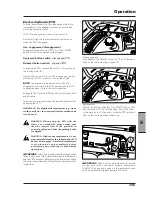
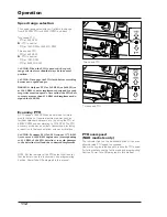
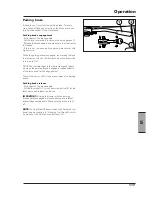
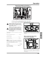
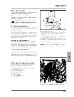
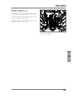
Power take-off operation
[4.2.d]
PTO mode selector lever (1).
The symbols on the decal beside the c ontrol lever have
the following meanings:
A - Independent PTO engaged.
Directly driven by the engine.
CAUTION:The selector lever should always be kept
in A position. Shift it to B only when the synchroni-
zed PTO has to be used. After the use of the syn-
chronized PTO shift the laver to A again.
B - Engagement of the ground speed synchronized
PTO (optional)
Driven by the gearbox.
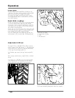
NOTE:
The PTO mode selector lever (1) has no neutral
position. This is obtained when the speed selector lever
(2) is shifted to the position “N”.
IMPORTANT:
The PTO mode selector lever, independent
or synchronized (optional), controls a mechanical coupler
that ensures the maximum safety in both operation modes.
The passage from a mode to another, however, is only
possible when the teeth are aligned. The procedure is
described under the headings “Direct power take-off” and
“Synchronyzed power take-off” hereunder.
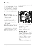
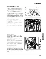
Power take-off engagement
- Select the required speed 540/540ECO/1000 RPM
with the selector lever (2).
- Engage the PTO mode selector lever (1).
- Engage the power take-off (3).
- During the work, the PTO can be engaged/disenga-
ged by means of the relative control lever (3).
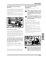
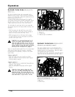
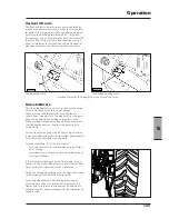
Direct power take-off
The direct PTO can operate at 540 RPM with the engine at
1944 RPM, or at 1000 RPM with the engine at 1956 RPM.
(At request 540ECO RPM with the engine at 1375 RPM).
The PTO is directly driven by the engine and its operation
is fully independent from the tractor’s ground speed.
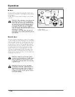
Engagement of direct PTO
The direct PTO must be engaged with the engine at
idling speed, without hesitating and not caring for any
noises which are due to the alignment of the gear
teeth.
Always keep the lever on the “A” position - direct PTO
engaged.
The synchronized PTO should be engaged only when
needed (see Synchronized Power Take-Off).
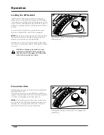
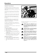
X60.50 Dual Power
The Dual Power system increases the available power
when working under load with engaged PTO. Dual Power
takes advantage of the potential of the electronic engine
control system to maintain steady power delivery even
when there are load variations. This is done by automa-
tically supplying an extra power reserve whilst the PTO
is being operated, thus allowing this latter to be used
in a better way while improving the performances and
productivity.
For power values, see the Technical Specifications chapter
in this manual.
Dual Power also engages to improve performances during
transport operation according to load, ground speed and
engine speed rate.
Summary of Contents for X60 Series
Page 39: ...39 Controls Cab 3 Section 3 Controls Cab...
Page 61: ...61 Instruments and Programming 4 Section 4 Instruments and Programming...
Page 90: ...90 Instruments and Programming This page has been left blank intentionally...
Page 91: ...91 Operation 5 Section 5 Operation...
Page 151: ...149 Tyres Wheels Ballasting 6 Section 6 Tyres Wheels Ballasting...
Page 168: ...166 Tyres Wheels Ballasting This page has been left blank intentionally...
Page 169: ...167 Maintenance 7 Section 7 Maintenance...
Page 229: ...Electrical system 227 8 Section 8 Electrical system...
Page 242: ...Electrical system 240 Page left intentionally blankf...
Page 256: ...Technical specifications 254 This page has been left blank intentionally...
Page 262: ...260 Alphabetical index...