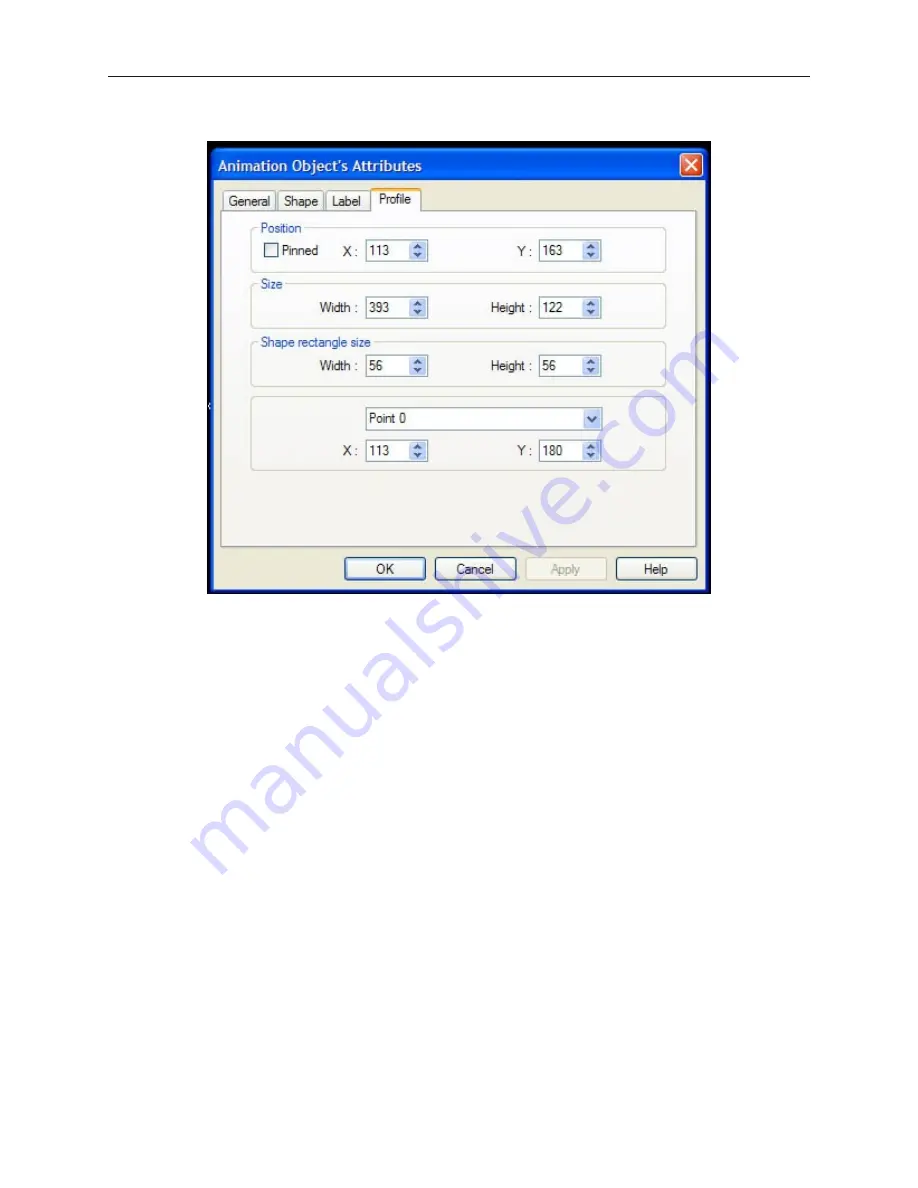
9.
Click on the
Profile
tab. The Profile dialog box appears.
10. The
Position
settings refer to the overall location of the Animation Object on the window
screen.
11. The
Size
settings refer to the overall size of the Animation Object.
12. The
Shape rectangle size
settings refer to the size of the shape or bitmap that you are using.
13. You can also manipulate the position of each point along the path of movement. Click on the
points pull-down box to select the point you wish to change, then edit the X and Y positions.
14. Click
OK
. The Animation Object’s Attribute form closes and the main screen of EasyBuilder
appears with the Animation part you just created on the screen. The shape you selected is
located at the first position on the path.
15. Once the part is placed onto the window, you can adjust the attributes by double-clicking on
the part to enter the Animation Object’s Attribute dialog box.
The next chapter shows how to construct a keypad for editing PLC data registers.
1010-1001a, Rev 02
200
Sil ver Se ries In stal la tion & Op er a tion Man ual
Summary of Contents for Silver HMI504T
Page 1: ...1010 1001A Rev 02...
Page 32: ...1010 1001a Rev 02 28 Silver Series Installation Operation Manual...
Page 128: ...1010 1001a Rev 01 124 Silver Series Installation Operation Manual...
Page 156: ...1010 1001a Rev 02 152 Silver Series Installation Operation Manual...
Page 166: ...1010 1001a Rev 02 162 Silver Series Installation Operation Manual...
Page 216: ...1010 1001a Rev 01 212 Silver Series Installation Operation Manual...
Page 251: ...1010 1001a Rev 02 Macros 247 Set Bit Objects Attributes Dialog Project Example of Add 2...
Page 264: ...End Macro_Command 1010 1001a Rev 02 260 Silver Series Installation Operation Manual...
Page 268: ...1010 1001a Rev 01 264 Silver Series Installation Operation Manual...


