


Grove
Published 01-14-2021 Control # 707-01
7-29
TMS9000-2 SERVICE MANUAL
POWER TRAIN
7
Removal
1.
Remove the transmission following the procedures
under
2.
Install two 19 mm (0.75 in) blocks of wood between the
clutch flywheel ring and the clutch release bearing
housing as the clutch mounting bolts are loosened
around the flywheel.
3.
Remove the bolts and washers mounting the clutch to
the flywheel.
4.
Remove the clutch assembly.
5.
If necessary, remove the setscrews and drive pins from
the flywheel.
Inspection
NOTE:
Failure to perform inspection may result in low
mileage disc/damper failure.
1.
Begin by wiping all surfaces before gauging.
2.
Secure the dial indicator to the flywheel housing with the
gauge finger on the flywheel near the outer edge. Rotate
flywheel.
3.
The total indicated difference between the high and low
joints must be 0.178 mm (0.007 in) or less for a 35.6 cm
(14 in) clutch, 0.203 mm (0.008 in) or less for a 39.4 cm
(15.5 in) clutch.
4.
Secure a dial indicator to the crankshaft. With the gauge
finger against the housing pilot, rotate the crankshaft.
Use a marker or soapstone to mark the high and low
points.
Total difference between high and low points should not
exceed 0.203 mm (0.008 in).
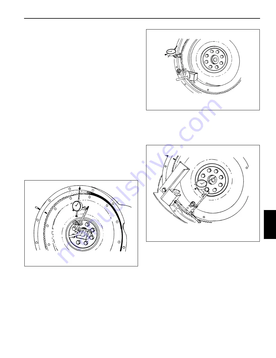
5.
Move the gauge finger to contact the face of the engine
flywheel housing.
Again, rotate the crankshaft and then mark high and low
points. The total difference between the high and low
points should not exceed 0.203 mm (0.008 in).
6.
Move the gauge finger to contact the pilot bearing bore
surface. Again, rotate the flywheel.
The maximum total allowable run-out is 0.127 mm
(0.005 in). If these limits are exceeded, the problem
must be corrected or misalignment will cause premature
wear to the drive train components.
4863-1
FIGURE 7-16
4863-2
FIGURE 7-17
4863-4
FIGURE 7-18
Fo
r
Reference
Only


