


4-42
Published 01-14-2021 Control # 707-01
SUPERSTRUCTURE
TMS9000-2 SERVICE MANUAL
(Figure 4-28) shows a region of a typical hydraulic schematic
for the Mechanical Locking Head Design. In the schematic
,
the highlighted actuator is shown to have a piston with rods
at both sides for the double-acting actuator. However, one
rod diameter is larger than the other. The other highlighted
area shows the rod diameters as 0.87" and 1.37". This
difference gives an exposed area difference for the hydraulic
pressure to act upon. If pressure is applied to just the left
side of the piston, then the actuator will shift to the right, and
this retracts the cylinder pins. If pressure is applied to both
sides of the piston, then due to the area difference, the
actuator will shift to the left, and this retracts the section pins.
As shown in (Figure 4-28), the setting of the Y2130 and
Y2131 valves can be manipulated to have the pressure
applied to one side or both sides (with appropriate relieving
of pressure where needed).
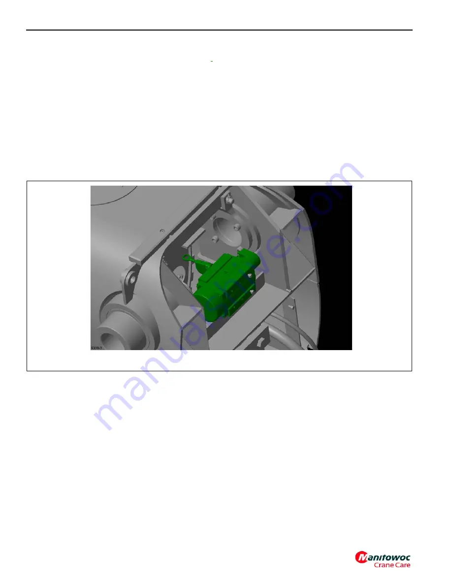
Precision Length Sensor Description
An important component of the pinned boom system is the
precision length sensor.(Figure 4-29) shows a typical
example highlighted in green with the back plates of the base
section not shown. This sensor has a cable reel. The cable is
attached to the pinning mechanism at the near end of the
telescoping cylinder barrel. As the barrel extends, the sensor
measures the distance. This distance is the most important
data that is used by the Pinned Boom Control System. It
allows motion to be monitored, and for the cylinder to be
placed in the correct location for pinning operations.
Pinned Boom Control System Description
The Pinned Boom Control System for the telescoping
system manages the state of the sensors, switches, valves,
and information to/from the display screens. There are a
number of different approaches to using the telescoping
system. These are referred to as the Semi-Auto Mode, the
Manual Mode, and the Emergency Mode.
It is important to realize that for some of the modes the
control system is performing automated motions within the
boom at some point in the telescoping process. At other
times, the operator is able to move the boom components.
Then the automated motions can occur once again after the
operator has indicated the appropriate next action for
telescoping the boom.
The control system requires that the telescoping cylinder and
pinning mechanism perform within expected parameters. For
instance, if there is entrapped air within the trombone-tube,
the hydraulic pressure will initially move the hydraulic
actuator as expected, but after the pressure is trapped in the
actuator and the pressure in the trombone-tube is reduced,
there may be motion of the components that is not expected
by the control system. If there is unexpected friction in the
sliding components, then the pressure may not be sufficient
to move the components within the time allotted by the
control system. If the boom is at a very low angle, the boom
sections may drift with respect to each other and then the
telescoping cylinder will not align with boom sections in the
expected range of the data from the precision length sensor.
Therefore, it is essential that the telescoping cylinder and
boom sections be maintained properly so that the control
system can work properly.
9300-3
FIGURE 4-29
Fo
r
Reference
Only


