background image

Ref.: MEL-WA(3D HCV) - OM Ver.1.7 

34


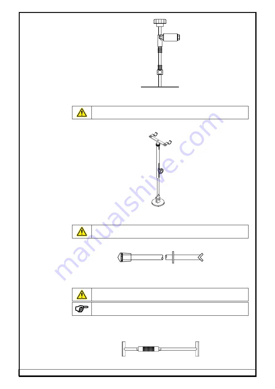
6.9.6. 

LCV STEERING LOCK 


Fig. 39 

Steering lock is used to arrest the movement / rotation of Steering wheel, 
while performing Runout measurement & Toe adjustment. 


Do not keep your head nearer to the Steering while locking with 
Steering lock to avoid get hit due to the spring tension 


6.9.7. 

HCV STEERING LOCK 


Fig. 40 

Steering lock is used to arrest the movement/rotation of Steering wheel, while 
performing Runout measurement & Toe adjustment. 


Do not keep your head nearer to the Steering while locking with 
Steering lock to avoid get hit due to the spring tension 


6.9.8. 

LCV BRAKE PEDAL LOCK 


Fig. 41 

Brake pedal lock is used to keep the Vehicle Brake in pressed condition 
(applied), so that the vehicle will not move during the Turn Left and Turn Right 
programs, which is very important to measure the Caster and Kingpin. 


Ensure the Brake pedal lock is pressed against the vehicle brake 


Ensure the Brake pedal lock is pressed against the vehicle brake 
during Caster & Kingpin swing to acquire readings 


6.9.9. 

HCV BRAKE PEDAL LOCK 

The HCV Brake pedal lock is suitable for HCV vehicles to lock the wheel while 
carrying out Caster & Kingpin measurement. 


Fig. 42 

Summary of Contents for JUMBO HCV

Page 1: ...3D WHEEL ALIGNER HCV model OPERATING MANUAL Ver 1 7...

Page 2: ...Wheel aligner leaving our Factory is in the best operating condition This OPERATING MANUAL has been prepared to help you in getting the best performance out of the equipment Still if you have any dou...

Page 3: ...ACCESSORIES refer scope of supply 32 6 9 1 WHEEL BRACKET HCV 12 to 24 32 6 9 2 ROTARY PLATE 7 ton 33 6 9 3 ROTARY PLATE SEGMENT PLATE 33 6 9 4 FRONT TARGET PLAT EXTENSION SPACER 150mm Lg 33 6 9 5 WHE...

Page 4: ...Axle 6A 5A 4A 77 7 4 5 20 TRAILER Forward parking 1 Rear Axle 6A 5A 4A 77 7 4 5 21 TRAILER Forward parking 2 Rear Axles 6A 5A 4A 78 7 4 5 22 TRAILER Forward parking 3 Rear Axles 6A 5A 4A 78 7 4 5 23 T...

Page 5: ...LTI USER 119 7 6 7 BACKUP RESTORE FACTORY CALIBRATION 119 7 6 7 1 BACKUP CALIB DATA FROM PC TO OTHER LOCATION 120 7 6 7 2 RESTORE CALIB DATA FROM OTHER LOCATION TO PC 120 7 6 7 3 BACKUP USER DATA FROM...

Page 6: ...sed for any purpose other than intended use 5 The equipment must be installed Indoor away from direct Sunlight or reflected Sunlight through any object or rain moist areas Warranty ceases if the equip...

Page 7: ...nt pit Alignment lift only 2 2 SAFETY INSTRUCTIONS FOR COMMISSIONING 1 Only Authorized service personnel are allowed to install and commission the Wheel aligner 2 Aligner should not be installed outdo...

Page 8: ...are locked with locking pins before parking the vehicle 13 Ensure gap filling spacers are located on Rotary plates before parking vehicle 14 Do not keep heavy objects over the equipment 15 Do not hamm...

Page 9: ...incorporated to protect the electronic components against high current The Fuse holders are mounted on the Interface box F1 F2 which can be easily accessed from outside for replacing the blown fuse A...

Page 10: ...ientific Imaging camera and 3D Imaging technology for measurement of angles using Align software 17 Windows Embedded Standard OS based Alignment program 18 LED primary display unit 19 LED secondary di...

Page 11: ...0 Zoom in option for Live parameters 11 Selectable functions 11 1 Display of Toe in degree min degree mm inch mm mtr other angles in degree degree min deg fraction i e 1 11 2Multi lingual program III...

Page 12: ...erature 0 to 50 C 3 Humidity RH upto 90 Non condensing 4 Machine dimension Unpacked WxDxH Vertical column 2 Nos 420x302x2893mm Main cabinet 770x695x1170mm 5 Machine dimension Packed WxDxH Vertical col...

Page 13: ...the owner s responsibility 4 3 SPACE REQUIREMENTS Installation area should have roof Floor should be of good concrete flooring and should be leveled surface Proof of safe floor load capacity is the o...

Page 14: ...Ref MEL WA 3D HCV OM Ver 1 7 9...

Page 15: ...Ref MEL WA 3D HCV OM Ver 1 7 10 Drive Through model...

Page 16: ...ge Regulator circuit using a CE certified Two Pole Type C 6A MCB Proper Earthing must be provided Also ensure that live phase is on the right side point of the wall socket Neutral to Line Voltage shou...

Page 17: ...are not set properly the effects will be uneven tyre wear loss of steering control pulling to one side while driving jerking on travel etc It may not be possible to correct all the above angles in a v...

Page 18: ...for improved steering and general handling performance In the past FWD vehicles and independent rear suspension vehicles were most likely to have adjustable rear Camber On vehicles currently being pro...

Page 19: ...gned with a static Toe in setting The static Toe in setting will become zero as the linkage flexes when the vehicle is in motion Always set Toe to the manufacturer s specifications On vehicles with To...

Page 20: ...road crown is compensated for along with Camber By setting the Caster angle on the Driver s side 1 2 degree less than the passenger side for Positive Caster specifications or 1 2 degree more for Nega...

Page 21: ...e closest to the road surface when the wheels are pointed Straight Ahead as a result of Kingpin Inclination A spindle with Kingpin Inclination will have the outer end of that spindle at the highest po...

Page 22: ...a varying degree of damage and or wear it is increasingly unlikely that the axles will be parallel When the rear axle projects a different angle than the front axle the driver will need to turn the st...

Page 23: ...axle and Tandem Dummy axle in a Multi Axle vehicle 5 7 PARALLELISM HCV Fig 11 PARALLELISM is the perpendicularity of the twin steerable axle s centre with respect to the Geometric centre line of the v...

Page 24: ...f they were under inflated Generally Setback is the result of collision damage It is preferable to have the front tyres square with each other before alignment is done The most accurate way of checkin...

Page 25: ...is the angle between a line drawn through both the wheel resting points A line perpendicular to the vehicle geometrical line thrust line will be measured in angles The measured angle will be displayed...

Page 26: ...ut affects the Camber TRUE VERTICAL 10 MINIMUM 30 AVERAGE 50 MAXIMUM ROAD Fig 17 Assume that there is a wobbling of 10 to 50 in a wheel and Runout is 40 max min reading This means when the vehicle is...

Page 27: ...calculations is automatic and average Runout compensation is achieved Above theory is also applicable for achieving the average Runout compensation in Toe setting Once Camber Toe Runout are compensate...

Page 28: ...to Rear Left wheel resting point Front Right wheel resting point to Rear Right wheel resting point Fig 20 The measured angle will be displayed as Positive angle if the Rear Track width is more than t...

Page 29: ...he wheels are steered to the right side Right wheel Lock Angle The angle turned by right wheel when the left wheel is External steered to max left is called Lock Angle External Right Lock angles for t...

Page 30: ...r to the plane of the left wheel from its centre Let b the angle turned by right wheel i e the angle made by the rear axle centre line produced and a line drawn perpendicular to the plane of the right...

Page 31: ...ories indicated will be supplied only against order 1 2 3 4 5 6 8 9 10 13 15 17 12 14 16 18 Fig 23 Sl No Description Sl No Description 1 Vertical Column Right 10 Main cabinet 2 Vertical Column Left 11...

Page 32: ...inet for distributing regulating power supply required for the Aligner Power outlets are provided in the panel for PC Peripherals Camera A High voltage cutoff MCB is also provided to protect the elect...

Page 33: ...s not in use 6 4 MAIN CABINET refer scope of supply Main cabinet is the housing for Desktop computer peripherals The Primary display unit is mounted on a Monitor column over the top of Main cabinet Se...

Page 34: ...ied Refer Desktop manual Soft media Follow the procedure given below to transfer the Warranty Ownership of Dell PC in case if supplied along with our Wheel aligner for claiming global Warranty Ensure...

Page 35: ...s Owner details and press Continue button Fig 29 Go through the instructions displayed and click Continue button Fig 30 Review the informations provided so far before agreeing to the Terms Conditions...

Page 36: ...the display dry Long term exposure to moisture may damage the display The location of Monitor power indicator and controls may change depending upon the make of the Monitor supplied Refer the Monitor...

Page 37: ...g pin in between the Tyre bead and the rim It may be necessary to pop the upper portion of the Wheel bracket with the palm of your hand to seat well Note that it is not necessary for the Wheel bracket...

Page 38: ...es Ensure the Top plate of Rotary plates are locked with Locking pins before parking the vehicle The Rotary plate must be maintained properly by user free from dust 6 9 3 ROTARY PLATE SEGMENT PLATE Ro...

Page 39: ...d nearer to the Steering while locking with Steering lock to avoid get hit due to the spring tension 6 9 8 LCV BRAKE PEDAL LOCK Fig 41 Brake pedal lock is used to keep the Vehicle Brake in pressed con...

Page 40: ...when not in use and for quick access during alignment Fig 44 6 9 12 ROTARY PLATE PIT SPACERS Pits spacers of following types are provided to arrest the movement of Rotary plates within its pit In case...

Page 41: ...of supply 6 10 1 WHEEL BRACKET HCV 15 to 28 The Wheel bracket is a versatile design to accommodate Wheel rims ranging from 15 to 28 of diameter 6 10 2 WHEEL BRACKET EXTENSION ADAPTER This Adapter is v...

Page 42: ...E CATCHING 3POINT CLAMP This accessory can be used for clamping the Wheel targets with Vehicle Tyre instead of Rim in order to avoid damages scratches to the Alloy rims This 3Point clamp can be used f...

Page 43: ...rder of Front Left Front Right Rear Left Rear Right Fig 56 6 10 12 DRAWBAR TOW BAR GAUGE FOR FULL TRAILER This gauge is used for conducting wheel alignment for Full trailer This Gauge will be mounted...

Page 44: ...be located at Front side and Rear side of Rotary plates so that the Vehicle can be rolled forward backward easily over the Rotary plates placed over a plain surface The Front and Rear Ramps are to be...

Page 45: ...ive Cartridge Model No Printer Make and Model No to the supplier Failing to comply may lead to Printer head damage improper printout Use only standard ISO A4 size papers 210 x 297 mm recommended by th...

Page 46: ...urb the camera path affect the reading stability Handle the Target plate carefully Rough handling shocks may cause damage to the Target plates 7 1 DEFECTS MALFUNCTIONS In case of defects or malfunctio...

Page 47: ...e Rotary plates are without sag or tilt while moving the vehicle over the Rotary plate 5 Ensure the Rotary plate pit spacer and Segment plates are without shake and with fits compactly Pit gap to be f...

Page 48: ...Rear axles having its nearest wheel base less than 4mtr park the Front steer axle at 2nd Rotary plate Fig 66 NOTE Use F1 Target plates for Front axle wheels B2 B1 Target plates for the respective Rea...

Page 49: ...arget plates for Front axle wheels B1 Target plates for Rear axle wheels For LCVs like Car Light truck with wheel base 4mtr Wheel diameter 24 park the Front wheels F1 on Front Rotary plate Fig 70 NOTE...

Page 50: ...ring Ball joints Tie rod etc thoroughly for any play looseness wear tear Replace the defective parts if any 12 Ensure that there is no excessive free play in steering mechanism Kingpin play and linkag...

Page 51: ...data Help To save Vehicle data Camera view To delete existing vehicle data To select the Vehicle To add User name password To enter the Vehicle data To edit User name password To view edit Vehicle In...

Page 52: ...tomer to access Special options Normally this Password must be kept as a secret by a responsible person say the Owner of the Shop If by chance the Password has come to other s knowledge a Password mod...

Page 53: ...ates in 4A model If required Press CTRL S to save the data and come to Desktop during alignment sequence any point of time If START ALIGNMENT button is pressed in Welcome screen user will be prompted...

Page 54: ...E SELECTION Select the required Vehicle databank from the following options in the screen Fig 76 If LCV databank is selected the following screen will be displayed On selection of required Vehicle dat...

Page 55: ...is explained below by considering a Truck with 2 Front axles and 3 Rear axles ie 5 Axles at a time For other Axle configurations refer Chapter 7 4 2 By pressing button specifications of selected vehic...

Page 56: ...Press PREVIOUS SCREEN button to go back to previous screen 7 4 2 WHEEL RUNOUT The purpose of this program is to find out the Wheel Runout wobbling and effect the Runout compensation automatically in t...

Page 57: ...els Vehicle drive should be very controlled constant movement Avoid sudden brake which will affect the measurement Steering lock must be applied While moving the Vehicle in Forward Backward direction...

Page 58: ...ns can be edited or selected respectively between Initial measurement completed and Alignment completed screens Press NEXT SCREEN after entering all the data In Push Pull Roll on Runout Vehicle should...

Page 59: ...measurement The following screen will be displayed Drive the vehicle backwards until the ball matches the green region in screen Truck with 2 Front axles 3 Rear axles Truck Bus with 1 Front axle 1 Rea...

Page 60: ...and till STOP symbol goes off Fig 89 Now drive the vehicle forward and to reach the home position Then Stop the engine Fig 90 Completion of Runout will be indicated by a Tick mark as shown below Fig...

Page 61: ...ure is required to measure these parameters Do not jerk or shake the Steering wheel during data acquisition Hold the Steering wheel at the end of each move to acquire stable measurement of Caster King...

Page 62: ...n region the system will display Stop icon and measures the parameters After data acquisition system will automatically go to Straight ahead screen 7 4 3 3 STRAIGHT AHEAD Fig 97 This screen is to inst...

Page 63: ...visually and then press NEXT SCREEN button as shown below to record Initial measurements of all parameters for prinout Fig 99 Now steer the Steering wheel to achieve zero in the following scren Fig 10...

Page 64: ...ion Red Reading is not within the required specification Green Reading is within specification preferred value White Specification is not available required for parameter Initial measurement results o...

Page 65: ...ruck with 2 Front axles 3 Rear axles Truck Bus with 1 Front axle 1 Rear axle Trailer with 3 Axles Forward parking Trailer with 3 Axles Reverse parking Car with 1 Front axle 1 Rear axle Fig 103 Fix the...

Page 66: ...oe Total Toe will be displayed Press ADDITIONAL PARAMETER button to view the Track width difference as shown in the following screen Fig 106 The Track width difference will be displayed as Positive an...

Page 67: ...t to that region Press ADDITIONAL PARAMETER button to view Kingpin Setback values Out of these three Runout Setback are having compensation with Camber and Toe respectively 7 4 4 4 DIFFERENTIAL TOE AD...

Page 68: ...zero the parallelism value will become zero 7 4 4 5 PARALLELISM ADJUSTMENT Press NEXT button to adjust the Parallelism The Parallelism screen will display the F1 straight position F2 Front axle Toe v...

Page 69: ...od Following procedure should be carried out to adjust Pusher Axle Toe Steer the Steering wheel until the Straight ahead reading reaches zero and then hold it Make the Pusher axle reading to zero by p...

Page 70: ...screen guidance as explained below Fig 118 Fix the Screw jack in between the two Axles as shown above Loosen the U bolts on the B1 Axle using Power tools and raise the Screw jack in such a way that t...

Page 71: ...achieve the required Toe and lock it Fig 123 7 4 4 9 CAM BUSH SHIM ADJUSTMENT Following procedure should be carried out to adjust Caster Camber on wheel free mode The actual values of Caster Camber ha...

Page 72: ...26 Details of Adjustment Methods BUSHING In this method the system displays the actual Caster Camber on Wheel free mode Now user has to enter the existing size of bush LA RA and its angle positioned L...

Page 73: ...V OM Ver 1 7 68 Fig 128 Fig 129 ADJUSTABLE BUSHING In this method User can adjust the Bush online to achieve the required Camber Caster instead of replacing the new Bush so that the user can save time...

Page 74: ...aster Camber User can select the required shim size for replacement and perform adjustment to achieve the Camber Caster within specified value Fig 132 Fig 133 STACK DRAG METHOD In this method user can...

Page 75: ...137 DEFAULT In this option user can select the required Bush for the replacement in upper control arm and perform adjustment to achieve the Camber within specification Fig 138 Steering lock Brake ped...

Page 76: ...get plates with Front axle F1 2 Mount Rear Target plates with Rear axle B1 3 Carryout Push Pull Runout by driving vehicle Ref Chapter 7 4 3 4 Carryout Caster KP swing for F1 Ref Chapter 7 4 4 5 Carry...

Page 77: ...Carryout Push Pull Runout by driving vehicle Ref Chapter 7 4 3 4 Carryout Caster KP swing for F1 F2 Ref Chapter 7 4 4 5 Carry out measurement as guided by the screen 6 Apply Steering lock at straight...

Page 78: ...se F2 B3 labeled Target plates 3 Carryout Push Pull Runout by driving vehicle Ref Chapter 7 4 3 4 Carryout Caster KP swing for F1 Ref Chapter 7 4 4 5 Carry out measurement as guided by the screen 6 Ap...

Page 79: ...F1 F2 11 Adjust Rear Pusher 3 rd axle B3 12 Adjust Rear 1 st axle B1 For adjustments refer Chapter 7 4 5 7 4 5 11 HEAVY TRUCK 2 Front Axles 3 Rear Axles including 1 Tag 1st Axle 6A 5A 1 Mount Front T...

Page 80: ...1 Mount Front Target plates with Front axle F1 2 Mount Rear Target plates with Rear axle B1 3 Carryout Push Pull Runout by driving vehicle Ref Chapter 7 4 3 4 Carryout Caster KP swing for F1 Ref Chapt...

Page 81: ...Rear axles B2 B1 3 Carryout Push Pull Runout by driving vehicle Ref Chapter 7 4 3 4 Carryout Caster KP swing for F1 Ref Chapter 7 4 4 5 Carry out measurement as guided by the screen 6 Apply Steering...

Page 82: ...ear Axles including 1 Tag Axle 6A 5A 4A 1 Mount Front Target plates with Front axles F1 F2 2 Mount Rear Target plates with Rear axles B2 B1 3 Carryout Push Pull Runout by driving vehicle Ref Chapter 7...

Page 83: ...easurement as guided by the screen 6 Adjust Rear 3 rd axle B3 7 Adjust Rear 2 nd axle B2 8 Adjust Rear 1 st axle B1 For adjustments refer Chapter 7 4 5 7 4 5 23 TRAILER Forward parking 4 Rear Axles 6A...

Page 84: ...7 4 3 5 Carry out measurement as guided by the screen 6 Adjust Rear 5 th axle B5 7 Adjust Rear 4 th axle B4 8 Adjust Rear 3 rd axle B3 9 Remove Rear B1 Target plates from Rear 3 rd axle B3 and mount i...

Page 85: ...s with Rear 1 st axle B1 2 Mount Rear Target plates with Rear 2 nd axle B2 3 Carryout Push Pull Runout by driving vehicle Ref Chapter 7 4 3 4 Carryout measurement as guided by the screen 5 Adjust Rear...

Page 86: ...LER Reverse parking 5 Rear Axles 6A 5A 4A Ensure the B1 axle is parked at 4mtr from the Camera 1 Mount Rear F1 Target plates with Rear 1 st axle B1 2 Mount Rear B1 Target plates with Rear 3 rd axle B3...

Page 87: ...ut by driving vehicle Ref Chapter 7 4 3 6 Carry out measurement as guided by the screen 7 Adjust Rear 1 st axle B1 8 Adjust Rear 3 rd axle B3 9 Adjust Rear 4 th axle B4 10 Adjust Rear 5 th axle B5 11...

Page 88: ...7 Adjust Rear 1st axle B1 8 Adjust Rear 3rd axle B3 9 Adjust Rear 4th axle B4 10 Adjust Rear 5th axle B5 11 Remove Rear F1 Target plates from Rear 1 st axle B1 and mount it with Rear 2 nd axle B2 12...

Page 89: ...Adjust Rear 5 th axle B5 11 Remove Rear F1 Target plates from Rear 1 st axle B1 and mount it with Rear 2 nd axle B2 12 Remove Rear B1 Target plates from Rear 3 rd axle B3 and mount it with Rear 6 th a...

Page 90: ...1 st axle B1 6 Swivel the Dolly as guided to center 7 Adjust Rear 2 nd axle B2 and also ensure the Drawbar gauge values are within specification For adjustments refer Chapter 7 4 5 7 4 5 34 FULL TRAIL...

Page 91: ...mera 1 Mount Rear B1 Target plates with Rear 1 st axle B1 2 Mount Rear B2 Target plates with Rear 2 nd axle B2 3 Mount Rear B3 Target plates with Rear 3 rd axle B3 4 Mount Front F2 Target plates with...

Page 92: ...1 Target plates 6 Adjust Rear 1 st axle B1 7 Swivel the Dolly as guided to center 8 Adjust Rear 2 nd axle B2 9 Adjust Rear 3 rd axle B3 and also ensure the Drawbar gauge values are within specificatio...

Page 93: ...lates with Rear 1 st axle B1 2 Mount Rear B2 Target plates with Rear 2 nd axle B2 3 Mount Rear B3 Target plates with Rear 3 rd axle B3 4 Mount Front B4 Target plates with Rear 4 th axle B4 5 Mount Fro...

Page 94: ...st axle B1 6 Swivel the Dolly as guided to center 7 Adjust Rear 2 nd axle B2 and also ensure the Drawbar gauge values are within specification For adjustments refer Chapter 7 4 5 7 4 5 40 FULL TRAILE...

Page 95: ...Target plates with Rear 1 st axle B1 2 Mount Front F2 Target plates with Rear 2 nd axle B2 3 Mount Rear B1 Target plates with Rear 3 rd axle B3 For 4A model use F2 B3 labeled Target plates 4 Mount Re...

Page 96: ...Rear 1 st axle B1 7 Swivel the Dolly as guided to center 8 Adjust Rear 2 nd axle B2 9 Adjust Rear 3 rd axle B3 and also ensure the Drawbar gauge values are within specification For adjustments refer...

Page 97: ...tes with Rear 1 st axle B1 2 Mount Front F2 Target plates with Rear 2 nd axle B2 3 Mount Rear B4 Target plates with Rear 3 rd axle B3 4 Mount Rear B1 Target plates with Rear 4 th axle B4 5 Mount Rear...

Page 98: ...ove 7 meter from Camera and press NEXT button Fig 140 Select the required User key in the password to enter into Vehicle selection screen Select the required Vehicle databank then the Vehicle Manufact...

Page 99: ...Runout measurement The following screen will be displayed Fig 143 Push the Full trailer backwards by 30 away from Camera by driving the vehicle or pushing manually until the ball matches the green re...

Page 100: ...146 Once the Stop symbol is displayed the system will proceed to next screen automatically Fig 147 Runout values will be displayed Press NEXT button to proceed further Fig 148 Fix the Drawbar in such...

Page 101: ...Thrust angle as per screen guidance and press NEXT button after completion Fig 151 Individual parameters of B1 axle will be displayed Press NEXT button to proceed Fig 152 Adjust the Dolly by swivelin...

Page 102: ...d press NEXT button Fig 154 Individual parameters of B2 axle will be displayed Press NEXT button to proceed Fig 155 Adjust the B3 axle and press NEXT button Fig 156 Individual parameters of B3 axle wi...

Page 103: ...e will be displayed Press NEXT button Fig 159 Both the B5 axle s Scrub angle and Drawbar s straight ahead will be displayed simultaneously Adjust both the parameters to achieve the target values and p...

Page 104: ...ion screen Select the required model configuration of the Full trailer Fig 163 Park the Full trailer in reverse parking as shown below in such a way that the B1 axle is at a distance of 4 5 meter from...

Page 105: ...get IDs with Axle IDs Enter required input in the Vehicle details screen and press NEXT button The system will identify the Target plates mounted on the wheels as shown below Fig 166 Press RUNOUT butt...

Page 106: ...eading acquisition and till STOP symbol goes off Fig 169 Now drive the vehicle forward to reach the home position Then Stop the engine Fig 170 Once the Stop symbol is displayed the system will proceed...

Page 107: ...as shown below Fix the Target plate press NEXT button Fig 173 Initial values will be displayed as shown below Fig 174 Adjust the B1 axle Thrust angle as per screen guidance and press NEXT button afte...

Page 108: ...arrow indicated on screen After achieving the value within range press NEXT button Fig 177 Adjust the B2 axle and press NEXT button Fig 178 Individual parameters of B2 axle will be displayed Press NEX...

Page 109: ...xle s Scrub angle and Drawbar s straight ahead will be displayed simultaneously Fig 182 Adjust both the parameters to achieve the target values and press NEXT button Individual parameters of B4 axle w...

Page 110: ...3 4 Carryout Caster Kingpin swing for F1 Ref Chapter 7 4 4 5 Carry out measurement as guided by the screen 6 Apply Steering lock at straight ahead position F1 7 Adjust Rear 2 nd Axle B2 Adjust Front 1...

Page 111: ...t 1 st axle F1 2 Mount Rear B1 Target plates with Rear 3 rd axle B3 3 Carryout Push Pull Runout by driving vehicle Ref Chapter 7 4 3 4 Carryout Caster Kingpin swing for F1 Ref Chapter 7 4 4 5 Carry ou...

Page 112: ...e Front F1 axle is at 2 8mtr from Camera in 1 st Rotary plate F1 axle should be within 7mtr distance from Camera and Rear 4 th axle beyond 7mtr distance 1 Mount Front F1 Target plates with Front 1 st...

Page 113: ...r 2 nd Axle B2 Move the Bus forward park Rear 2 nd axle B2 in 1 st Rotary plate B2 axle should be within 7mtr distance from Camera Rear axle B1 beyond 7mtr 15 Remove Front F1 Target plates from Rear 3...

Page 114: ...User Interface This software is designed to retrieve the stored alignment results and to generate reports The following screen is the Opening screen of this software Fig 185 Four options will be disp...

Page 115: ...W button to view the Date based reports as shown below Fig 189 Press PRINT button to print the report 7 5 2 REGISTRATION NUMBER BASED ALIGNMENT REPORT This report helps the user in deciding the freque...

Page 116: ...be displayed based on Job number By selecting tab of respective axle in the screen results of respective wheel parameters can be viewed Press VIEW button to view Registration No based reports as shown...

Page 117: ...rt 7 5 4 TECHNICIAN BASED ALIGNMENT REPORT Upon selection of Technician based alignment report icon the available User s list will be displayed Fig 196 Select the required User From To date and then p...

Page 118: ...e date based Customer details as shown below Fig 199 Press PRINT button to print the report 7 5 6 REMINDER TO CUSTOMER This option is provided to the user to generate Reminder letters to his customers...

Page 119: ...ovided in the Data Manager program to delete the data with following options Within a period or Job number wise or All the data Press HOME button and then select TICK mark to exit from Data Manager pr...

Page 120: ...IONS The Vehicle specification data must be entered by End user only MANUFACTURER IS NOT RESPONSIBLE FOR ANY INCORRECT OR INCOMPLETE VEHICLE SPECIFICATIONS ENTERED AVAILABLE IN THE SYSTEM No claim is...

Page 121: ...DATA button to User data for edit customizing the specification 7 6 1 4 INDIAN LCV DATA The readily available vehicle specifications that are compiled and released by manufacturer in our system These...

Page 122: ...h wheel to enter the Maximum and the Minimum permissible reading 5 CASTER Enter the Minimum allowable Caster for that vehicle in first data window Enter the Maximum allowable Caster in second window A...

Page 123: ...and password settings Customer can also add Logo of their Service centre to appear on the top left corner of the printout Also option is provided to add the Distributor Logo which will appear at the b...

Page 124: ...o delete the Logo provided already 7 6 5 CALIBRATION HISTORY The details of Target plate calibration done so far can be viewed in Calibration history To take a printout press PRINT button or to save i...

Page 125: ...ate the source of calibration files for restoration The files are provided along with the Aligner in Optical media format Also a backup is stored in local HDD of Personal computer Once the data are re...

Page 126: ...is option is provided to activate the optional features from field and to reset the User password 7 6 9 1 LOCK DETAILS The Optional features available in the alignment programs are controlled using bu...

Page 127: ...word If entered password is not correct Invalid Password message will be displayed If the entered password is correct the operator will be prompted to enter the New password Then re enter the new pass...

Page 128: ...the preferred language out of the available options so as to display the alignment screens and Voice prompts in their regional languages Press LANGUAGE button in the Welcome screen and select the lan...

Page 129: ...eived from the IR source Therefore it is the responsibility of User to keep the Target plate clean and free from dust scratches The following tips will help the end user to maintain the Target plates...

Page 130: ...should have approx same amount of thread wear Incorrect Caster setting Caster must be same on Front wheels Check for worn out Control arm worn strut rod bushings Dragging brakes and car pulls sideway...

Page 131: ...d pressure and adjust the Camber as per the specifications Tyre wear on inside shoulder due to excessive negative Camber Inflate the tyre to recommended pressure and adjust the Camber as per the speci...

Page 132: ...l rim and ensure the bracket motion is proper If not replace the particular Wheel bracket 3 Fix all the Wheel brackets in a particular wheel one by one and ensure the readings are similar Uneven pit l...

Page 133: ...Turn angle from misaligned Tie rod or bent Steering arm Low or uneven tyre inflation Align the Tie rod and adjust the Lock angle and check the tyre pressure Unstable at high Speed due to incorrect Fr...

Page 134: ...data cable and reconnect it to the system with correct polarity No loose connection in Data cable Still the display problem persists Monitor may be defective Replace a monitor from other computer and...

Page 135: ...acturer All information illustrations and specifications contained in this Manual are based on the latest information available at the time of publication Manufacturer reserves the right to make chang...

Reviews:

Related manuals for JUMBO HCV