background image


Joint  Robot  Manipulator  -  Software  Operation  Manual 


Advantech LNC Technology Co., Ltd.


44 


Move after waiting for arriving the position 

Arriving: 1/1000 degree, or 1um 


Note: The range of arriving will only be checked 

after the commands have been sent. So, setting a 

very large value may not have the desired effect. 


11.1.3.


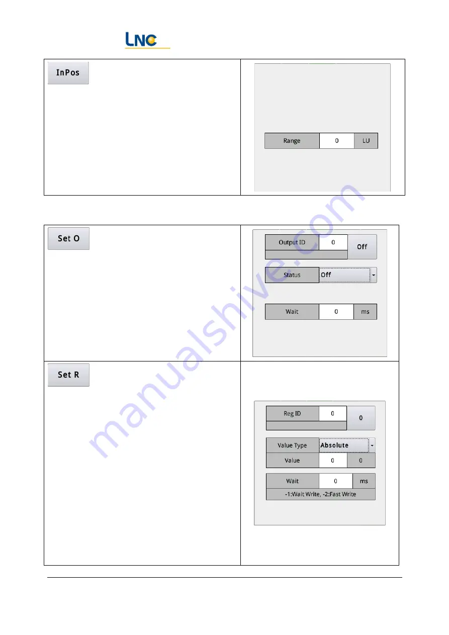
Status setting 


Set the status of point O 

Number: the number of the point O 

Value: Off, On, commutation (change to another 

state based on the current state of the point O) 

Wait: Set how long to wait before executing the 

next line. 


Set the content of R value 

Number: the number of R value 

Type of value: 

Absolute: directly set the content of the R 

value to the content in the "Value" field. 

Relative: Accumulate the content of the Value 

field based on the content of current R value. 

No.: Set the R value of the specified R number 

in the Value field to this R value. 

Add 1 to the circulation: Add 1 to the current 

R value and set it to 0 when the value is 

greater than the set value in the Value field. 

Value: Reference mode description 


Summary of Contents for Robot Series

Page 1: ...ation Manual Error Use the Start tab to apply title 1 to the words you want to display here Advantech LNC Technology Co Ltd 1 Robot Series Joint Robot Basic Operation and Program Manual Leading Numerical Controller 2018 12 Ver V09 00 ...

Page 2: ...ns 15 3 4 IO 15 3 5 Alarm warning page 17 4 Introduction to basic concepts 18 4 1 Introduction to space coordinates position and attitude 18 4 2 Various coordinates and their relevance 20 4 3 Fast moving 21 4 4 Path motions 21 5 Maintenance and teaching mode 24 5 1 Button names 24 5 2 Mode description 24 5 3 Differences between handwheel and non handwheel modes 25 5 4 Coordinate system selection d...

Page 3: ... 3 Status setting 44 11 1 4 Motion command 45 11 1 5 Function module calling 48 11 2 Extended instructions 50 12 Use coordinate system to simplify programming and maintenance 60 12 1 Setting XYZABC directly 60 12 2 World Record XYZ 60 12 3 World record XYZABC 60 12 4 Coordinate system record 61 12 5 Current position and attitude 61 12 6 Dynamic position and attitude 61 12 7 Joint record 62 12 8 Se...

Page 4: ...Joint Record Movement G10 82 17 11 World record movement G11 82 17 12 Set whether the command of the axis output G13 83 17 13 Get the world coordinates G17 G1T17 of the final position 83 17 14 Get the work coordinate G18 G1T18 of the final position 83 17 15 Get the joint coordinates G19 G1T19 of the final position 84 17 16 Wait for Point I G20 84 17 17 Wait for R value G21 84 17 18 Set O G22 85 17...

Page 5: ...em G57 90 17 27 Start dynamic compensation G61 91 17 28 Turn off dynamic compensation G60 91 17 29 Interpolation table conversion G69 91 17 30 Set the flexibility level G89 91 17 31 Set the synthetic acceleration deceleration time G90 92 17 32 Set the shaft speed smoothing time G91 92 17 33 Set the shaft speed tolerance G92 92 17 34 Serve lag eliminates and updates coordinates G95 92 17 35 Update ...

Page 6: ...ctions The light signal shows the current alarm and the button reset system equivalent to the reset button on the screen Other buttons Refer to the description of following sections Handwheel Emergency USB interface Rate percentage adjustment Start Pause Stop Custom button F1F2 Screen lock Operating mode switch Manual operating coordinate system selection handwheel operation switching rate multipl...

Page 7: ...oint Robot Manipulator Software Operation Manual Advantech LNC Technology Co Ltd 7 2 2 Instructions for screen configuration Title Bar Page Display Area Left Function Menu Area Right Quick operating Area ...

Page 8: ...Cancel it will display a small square of Forbid in the upper right corner Click it and the password window will pop up again Click on the upper half to switch the start status of servo Displays the rate percentage of the system operating speed in the current system state and automatic mode Not ready It will stay in this state until the coordinates of any of the motors are not confirmed In this sta...

Page 9: ...rning Click Reset to clear the current alarm warning if the establishment condition for the alarm warning has disappeared Press this button to switch the A870 to put the system into an emergency stop state The system s emergency stop can be triggered by multiple sources handheld box upper software electric cabinet external signal 2 4 Right quick operating area Handwheel mode switch whether to oper...

Page 10: ... specific action on each page Teaching Move with the coordinate system direction such as world work tool and joint as a reference 2 5 Left function menu The buttons displayed on the left are arranged as standard version of the function items which can edit the page and add the linked function buttons according to the application requirements Each button is linked to the corresponding function page...

Page 11: ...e control mode is bus absolute this function is unnecessary Normally the coordinate reset will be completed automatically after each emergency stop state is released Note 2 The operation of setting the coordinates will be different depending on the use of absolute motor If absolute motor is used the set coordinates will directly read the motor s encoder and convert it to the coordinates in the con...

Page 12: ... by the motion process developer to write the motion process Please ask the machine factory for the default password 3 Machinery factory used by the machinery factory that manufactures robots responsible for robot debugging origin calibration limit and authorization settings Please ask the machine factory for the default password 4 System level used by the person responsible for system settings re...

Page 13: ...d Enter the current password new password confirm password and press Change 3 3 Coordinates This page contains coordinate system display and setting coordinate display coordinate motion function When login with administrator or above and in the teaching mode all functions of this page can just be used 3 3 1 Coordinate system and settings ...

Page 14: ...t as preset Set the current coordinate system value to the default coordinate system for the next startup Origin Move straight to the origin of the coordinate system move when pressed and stop when released Calibration point To the calibration point position marked on the startup page move when pressed and stop when released 3 3 2 Current coordinates display Display current world coordinates work ...

Page 15: ...tion on the title bar Close Close window of coordinate page 3 3 3 Operation for motions Coordinate selection You can select the coordinates of World Work and Joint Coordinate input You can click the coordinate value field to input the value directly or press Select Current to bring the current coordinate value first and then modify it for specific items Move to coordinates Press To to move to the ...

Page 16: ...O Digital output signal AI Analog input AO Analog output TCI Temperature sensing input R Register G G code M M code Ins Insert macro Update Used in the development phase of the developer to re read the contents of definition files of the resources Cancel Close this window Note 1 The sample files of the user defined resource can be obtained from ReconTool File language UserString_0000 str ...

Page 17: ...ows current and historical alarms and warnings Note 1 The user defined alarm warning exists in ReconTool file language UserAlarm_0000 str which can be downloaded and edited and then uploaded to overwrite the original file The alarm range is from R29000 00 to R29049 31 and the warning range is from R29050 00 to R29099 31 ...

Page 18: ...efined in the center of the base If you think of the manipulator arm as a person the direction of the XYZ axis is the same as the direction of our well known axis The right side is X the front is Y and the above is Z In addition to the position in space the Ptool also contains the axis representing its attitude Pwork is designed to facilitate offline programming and to allow multiple groups of rob...

Page 19: ...to indicate the possibility of various directions A more detailed description can be found by searching the Internet for Euler s rotation theorem The rules of Euler s rotation theorem are not necessarily the same in each robot system LNC s Euler s rotation theorem is defined as ZXZ and the universal is the right hand rule ie A is the angle of rotation around the Z axis B is the angle at which the ...

Page 20: ... is converted visual mechanism state in appearance World coordinates The position and attitude of Ptool when the center of the manipulator base is the origin Forward kinematics An algorithm that converts motor coordinates to world coordinates Inverse kinematics An algorithm that converts world coordinates to motor coordinates Work coordinates Converted from world coordinates points through the wor...

Page 21: ...t point can be reached most quickly but since the attitude change in the actual conversion process is related to the current coordinate the change process cannot be ensured Therefore it s necessary to be careful when using it 4 4 Path motions The path motion is a reference point for the path calculation of the Ptool In addition to the spatial position the attitude change should also be considered ...

Page 22: ...s 1 Three point linearity The starting point the midpoint and the end point are divided into two straight lines to change the attitude 2 Two point linearity Ignore the midpoint s attitude and change the attitude by the arc length ratio 3 Three point arc The starting point the midpoint and the end point are divided into two arcs and the attitude is changed along with the arc plane 4 Two point arc I...

Page 23: ... plane If the end point uses the arc endpoint command you can additionally specify the angle that the arc will around in total The center of the arc can specify the way the attitude changes The attitude change refers to the items 2 4 5 6 and 7 of the three point arc Note The attitude change has its practicality in some processing applications Please select the appropriate method according to actua...

Page 24: ...on Motion buttons When the button light is on it means that the button will work when pressed If it is not lit it will not work 5 2 Mode description Maintenance mode Rotate the motor it can still move when the preparation is not ready and it can still run away from the limit when the axis exceeds the limit Teaching mode It operates according to the type of coordinates required and cannot enter the...

Page 25: ... multiplier x handwheel rotation rate Incremental control Select non contiguous It moves some distance if pressed for one click and the distance is determined by the speed multiplier Rotate grid by grid Position control e g To on multiple pages To button moves when pressed and stops when released Press To to enter the motion state when the handwheel rotates forward it advances and when the handwhe...

Page 26: ...y Co Ltd 26 5 4 Coordinate system selection during motions Depending on the selected coordinate system the direction of XYZ motions is determined by the selected coordinate system Joint coordinate system Defines the decision based on the direction in which the joint rotates ...

Page 27: ...the end axis of the orthogonal robot Rotate the XYZ axis of the selected coordinate system to maintain the same angle with the coordinate axis and rotate in different directions Regardless of the currently selected coordinate system it is forced to change to the direction of the tool It can be imagined that people sit in the Ptool the eyes are facing Y direction the joystick is in the hand A A is ...

Page 28: ...meters contains six items where offset X offset Y offset Z describes the relative position between the Ptool and the flange face angle A angle B and angle C describe the direction of the point Tool calibration steps 1 Click the tool number 0 3 to be corrected for example 2 Click the item to be corrected and press 3 The robot moves to the attitude of the right figure while a point is installed exte...

Page 29: ...nd 9 Press and to see the value 10 Click the value on to add the error to tool parameters 11 If the direction of the Ptool is not parallel to the axis of the sixth axis you need to set the tool angle First set the tool angle A angle B and angle C to 0 12 Click the item to be corrected 13 Turn the direction of the Ptool so that the tool direction is consistent with the direction of the world coordi...

Page 30: ...cessary to modify the programming content on site Update to the currently selected world record with current world coordinates The linear path is calculated according to the current position and the target position Update to the currently selected joint record with the current joint coordinates Move to the selected joint record position in a fast moving manner Note 1 The point record can be used a...

Page 31: ...oordinates check interval and the position interval can be set through the following page Get the current coordinate value and set it as the coordinate of the security point Move to the security point position Moves when pressed and stop when released Note 1 can be set on the option page If the robot s point is wrong when starting it will directly send an alarm to avoid the danger of collision Not...

Page 32: ...to meet the needs of multiple sets of processing areas The following figure can be divided into two areas the left side is used to view the current coordinate system record and the right side is a three point coordinate system method to help calculate the positional offset direction rotation and tilting of the coordinate system After the coordinate system is determined using three points it can be...

Page 33: ...selecting the relative position of the object in the working area and the manipulator arm the three point coordinate system can be set The operation mode is as follows 1 First select the origin P0 and P1 P2 to be used as the basis for the calculation of the coordinate system 2 First adjust the robot to an appropriate attitude and align to P0 P1 P2 3 According to the axial direction where P1 and P2...

Page 34: ...ts in the setting range and put them in the internal clipping area Copy Copy all the contents of the setting range and put them in the internal clipping area Paste Paste the contents of the internal clipping area onto the position of the selected column in the list Offset XYZ Offsets all the items of world coordinates and work coordinates in the set range from the set value Modify speed Change all...

Page 35: ...ystem used in the current teaching or specifying which coordinate system to record Keys Record command Command parameters Select coordinate system Select coordinate system The coordinate system selected is used as the recorded coordinate system Fast path Fast path If the Select Coordinate System function is not on the coordinate system of the teaching motions is used as the recording coordinate sy...

Page 36: ...list The following sections are described in detail 10 1 4 Extended instruction Extended instructions contain some common features either to make the program list easier to read or to include a composite motion flow in a single instruction After clicking one of them the item details of the item will appear for editing After editing press OK to add the instruction to the program list The following ...

Page 37: ...olumn in the list Up Moves the currently selected column up Down Moves the currently selected column down Back If the current position is matched with the selected command line pressing this button to let the robot return along the path until the previous command point Forward If the current position is matched with the selected command line pressing this button to allow the robot to forward along...

Page 38: ...ich to create save and open the program files 10 3 2 Record continuous track and IO motion 1 Switch to teaching mode and click Record 2 Move the robot to the target position with a button or handwheel 3 Set Select coordinate system 4 Click on the line or other action command 5 Repeat steps 2 4 to complete the action flow Program display mode Number of workpieces Number of workpieces Operation mode...

Page 39: ...e trajectory is deviated you can adjust the position then press and archive then continue to use the Forward and Back to test to correct the trajectory 10 3 4 Handwheel run test 1 Cut to automatic mode and select the handwheel 2 Press Start to rotate the handwheel to let the program run at the speed of the handwheel 3 If you think that the program does not work as expected you can reset the progra...

Page 40: ...ch to automatic mode again 6 Click to change it to 7 Press Start to continue the unfinished run test 10 3 5 Operation observation of Repeat 1 Click to change it to 2 Close the handwheel 3 Start the program observe the effect of repeated running and continuously adjust and optimize to the best ...

Page 41: ...Basic instructions 11 1 1 Process Control Set the label of the command line for the reference of skipping setting Skip directly to a line Line number type Absolute line number ie the actual program line number Relative line number relative to the current line of line number for example currently line 8 4 means skipping to the 8 4 line ...

Page 42: ...on Skip to the specified line when the conditions of I or A meets the requirements No number of point I Value When the state of point I is in accordance with this setting the skip action is performed Skip mode refer to skip command When the condition of R matches skip to the specified line No R value number Comparison method Value Constant fixed value R value refer to the content of another R valu...

Page 43: ...s performed Waiting The longest waiting time Failure processing processing after waiting time Continue operating after waiting for R value to match the status No R value number Comparison method Value Constant fixed value R value refer to the content of another R value Right box constant value R value number Skip mode refer to skip command Waiting The longest waiting time Failure processing proces...

Page 44: ...hange to another state based on the current state of the point O Wait Set how long to wait before executing the next line Set the content of R value Number the number of R value Type of value Absolute directly set the content of the R value to the content in the Value field Relative Accumulate the content of the Value field based on the content of current R value No Set the R value of the specifie...

Page 45: ...e of the world record directly based on the record number Current world coordinates Display current world coordinates Point type fast linear Flexibility input blank or 0 5 corresponding to the setting of debugging page Speed If the speed is 0 it means the default linear speed is used 1 100 represents the percentage of the set speed in the debugging page Record number based on the record number Abs...

Page 46: ...om the process offset position to the original position Start process If the process is not started this command will generate a linear path that moves the current position to the process offset position If the process is already enabled this command will generate a linear path that moves the current process offset position to the new process offset position Process coordinate system The coordinat...

Page 47: ...n the Max Range of Process column in the Options Page Run otherwise the alarm will pop up Absolute relative The content representing the set value is either absolute to the selected coordinate system or relative to the current coordinate of the target coordinate system Coordinate system the coordinate system used to represent the contents of the set value Flexibility input blank or 0 5 correspondi...

Page 48: ...ates are used lPoint type fast linear Flexibility input blank or 0 5 corresponding to the setting of debugging page Speed If the speed is 0 it means the default moving speed is used 1 100 represents the percentage of the set speed in the debugging page 11 1 5 Function module calling Call G code built in by the system or manually written by the developer to provide greater flexibility Parameter A 1...

Page 49: ...Joint Robot Manipulator Software Operation Manual Advantech LNC Technology Co Ltd 49 transmitted to the G code Parameter L 12 The sixth parameter to be transmitted to the G code ...

Page 50: ...cal process packages The contents of many task packages need to be combined with additional page settings Because there are many scopes this document contains detailed instructions for the instructions and pages Please ask the machine for instructions Used to dynamically switch the tool groups set in the tool page or dynamically set the desired tool parameters ...

Page 51: ...pace It is used to dynamically switch the coordinate system record set in the coordinate system page The use can easily see the current coordinate system in the program list It is used in applications where the robot clamps the workpiece for path editing such as polishing When the working coordinates are reversed the three point arc of the workpiece surface can be realized which can greatly reduce...

Page 52: ...the punching machine as the quantity decreases the suction position changes It can be judged whether the reclaiming position is reached by the sensor mounted on the tool during the process of lowering the reclaiming With the settings in the security point page check whether the current position is within the range of the security point and provide the function of moving the position of the securit...

Page 53: ...am pause put the program into a pause state Wait for the torque to reach the start the action is in a waiting state until the torque of a certain axis arrives and then continue to run the subsequent action Issue warning when Wait I timeout it is equivalent to Wait I command but if the waiting time is exceeded a warning signal will be issued ...

Page 54: ...oftware Operation Manual Advantech LNC Technology Co Ltd 54 Dynamically switch the flexibility settings in the debugging page You can call the program login the program list page or the O files exported from the block operation ...

Page 55: ...ch LNC Technology Co Ltd 55 The image files login the map files list page can be loaded and the path directly from the image file to the corresponding processing action is operated by the system Match the settings of the matrix page to perform related actions ...

Page 56: ...Joint Robot Manipulator Software Operation Manual Advantech LNC Technology Co Ltd 56 Use the settings of the stack page to perform related actions ...

Page 57: ...ine When the folding machine bends the sheet metal the robot must follow the path of the sheet metal bending for movement Used for a command for positioning the additional axis separately when the additional axis is not in motion with the body Follow the EUROMAP67 specification for the signal communicating with the machine The system has four sets of peset machine ...

Page 58: ...f signals When the command between the start and the stop is running if the signal of the I point is detected to be inconsistent with the state that it should be an alarm will be issued It can be used in the process of taking workpieces to detect the use of falling workpieces When used in welding the workpiece cannot be accurately placed It is necessary to touch the surface of the workpiece throug...

Page 59: ...Joint Robot Manipulator Software Operation Manual Advantech LNC Technology Co Ltd 59 system ...

Page 60: ...of the applicable timing for various setting of the coordinate system options 12 1 Setting XYZABC directly Fill in the value of the coordinate system directly It is suitable for use when inputting values arbitrarily in the development environment or when the coordinate system is fixed 12 2 World Record XYZ Set position X Y Z in the set world record number to Work coordinate system but set A B C to...

Page 61: ...ed to calculate the coordinate system by taking three points such as coating adhesive cutting and other uses 12 5 Current position and attitude Set the world coordinate position X Y Z and A B C when the program is executed to this line to the work coordinate system It is suitable to perform multiple moves according to the position after moving to a certain position while teaching the recording pro...

Page 62: ...parameters 12 8 Setting the joint coordinates directly Same as the previous option except that the coordinate values are direct inputs and are typically used for development environment testing 12 9 Re offset direct setting Based on the current work coordinate system the work coordinate value at a certain point is converted to world coordinates to replace the original work coordinate system It s u...

Page 63: ... Manual Advantech LNC Technology Co Ltd 63 13 List The list page is used to put program files into the list for easy recalling 13 1 Put the program into the list 1 Switch to teaching mode 2 Click 3 Select the file intended to put and press Open ...

Page 64: ...n use I55 to start the program 13 3 Appoint to execute 1 Switch to automatic mode 2 Press to execute the appointed programs in order 3 The appointed number represents the order number of execution 0 means not scheduled 1 means being executed and 0 means the current order 4 Press and hold the button of appointed number for a sufficient amount of time to perform the appointment cancel the appointmen...

Page 65: ...ich can be cleared after pressed and released Note 1 I730 I749 correspond to the buttons of 20 appointed numbers respectively and they operate in the same way Note 2 O730 O749 corresponds to the status of appointment of the 20 sets of list program It is always on when it is being appointed flash when it is appointed and off when it is not appointed ...

Page 66: ...ation Manual Advantech LNC Technology Co Ltd 66 14 Composition of Program Modularization The program page has multiple ways to call module files 14 1 Calling program files Call the program files that previously placed in the list page 清單頁 ...

Page 67: ...Joint Robot Manipulator Software Operation Manual Advantech LNC Technology Co Ltd 67 14 2 Calling O files Calling the O files exported by another program ...

Page 68: ...Technology Co Ltd 68 Note The exported files are the most basic format which can save the program files from being converted at runtime and the efficiency will be higher The figure below is the content exported by the above program which is the G code format of text ...

Page 69: ...Joint Robot Manipulator Software Operation Manual Advantech LNC Technology Co Ltd 69 14 3 Calling G files ...

Page 70: ...n Manual Advantech LNC Technology Co Ltd 70 Note The incoming parameters when the exported G code cannot be connected to the calling of upper layer can be achieved to receive parameters by writing the G code and run according to the parameters ...

Page 71: ...nded to write at PC and then pass it to the controller 15 1 Types of files Save location NCFiles Folder Macro Folder Macro Folder Rules of file names Arbitrarily maker_macro_g1000 maker_func_ins_macro1000 NC executing page Name of Start files Start No External executing mode R17022 R17029 File name R23030 1 C0 1 R17004 1000 C22 1 Files operation View mode Software keyboard Operation of program lin...

Page 72: ...for example O1234 which can be called with G65 P1234 The G code format can be written as described in the last two sections 15 2 Viewing and editing methods Full screen It is convenient to see more lines of code When you click to edit a soft keyboard pops up Embedded Reduce page jumps click on the line of code when editing and then type directly in the keyboard below ...

Page 73: ...code 16 NC execution This page can be used to run the machining path files GM code generated by CAM or the files exported by the program page or the files edited manually by the user These files must conform to the G code format requirements of this robot system For detailed G code and program syntax please refer to the last two sections Switch path Jump to line number Select the files to run Swit...

Page 74: ...ly maker_func_ins_macro1000 File selection Click the File Name button and select the file Enter the number of the inserted file Start button 16 2 Viewing mode Program code Drawing Display Option of Change Switch the number of lines you can see Note Because it needs to take CPU time for the system to update the displayed lines only five lines are displayed by default Set the relevant parameters of ...

Page 75: ...Joint Robot Manipulator Software Operation Manual Advantech LNC Technology Co Ltd 75 ...

Page 76: ...nd directly specify the space speed between the two small lines Examples G00 X100 Y100 Z10 A0 B0 C39 F4000 G1 T2 X100 Y100 Z10 A0 B0 C39 F4000 Move to the position of the work coordinates 100 100 10 0 0 39 at 4000 deg min G00 L0 X100 Y100 Z10 A0 B0 C39 F4000 G1 T2 L0 X100 Y100 Z10 A0 B0 C39 F4000 Move to the position of the world coordinates 100 100 10 0 0 39 at 4000 deg min G00 M1 X100 Y100 Z0 F4...

Page 77: ...ription Linear S0 Arc transition S1 Arc midpoint S2 Arc center S3 Arc end point S4 D Attitude change mode 0 Three point linear 1 Two point linear 2 Three point arc 3 Two point arc 4 Fixed starting point 5 Starting point AB 6 Starting point ABC Rotational direction 0 Set by point preset 2 Forced along the arc 3 Forced reverse arc R Bypassed angle O Output point number P Start point distance Q End p...

Page 78: ...e position of the world coordinates 100 100 10 0 0 39 at a speed of 4000 mm min G1 M1 X100 Y100 Z0 F4000 Move straight at a speed of 4000 mm min to the position relative to the current work coordinates 100 100 0 G1 L0 M1 X100 Y100 Z0 F4000 O201 P30 Q20 Move straight at a speed of 4000 mm min to the position relative to the current world coordinates 100 100 0 Set O201 on at 30mm from the starting p...

Page 79: ...he center of the arc the work coordinate 100 100 10 as the end point of the arc to draw a clockwise arc and the attitude at the end of the arc is 0 0 39 17 2 5 Arc End Point S4 Use G1 T5 S2 to set the point on the arc and G1 T5 S4 to set the end point of the arc G1 S2 X100 Y90 Z80 G1 S4 X100 Y100 Z10 A0 B0 C39 F4000 Starting from the current position the work coordinates 100 90 80 are a point on t...

Page 80: ...int of the arc to draw a clockwise arc and the attitude at the end of the arc is 0 0 39 17 4 Wait G4 Code description X waiting seconds P Waiting milliseconds Examples G4 X1 P200 Waiting for 1200 milliseconds 17 5 Switch tool parameters G5 Code description L The tool parameter group is 0 3 If not specified the direct setting value of XYZABC is used X Tool parameter X Y Tool parameter Y Z Tool para...

Page 81: ...0 World coordinates 1 Work coordinate 2 Tool coordinate 3 Path X Tool Z 4 Path X Work Z 5 Path X World Z Q Style category 0 Round 1 Front and rear 2 Left and right X Moving range X speed R number Y Paragraph distance Y speed R number Z Initial movement Z speed R number Examples G7 E0 Disable path process G7 E1 L0 Q0 X10 Y8 Z0 Use regular pattern process world coordinate system circling mode circli...

Page 82: ...h axis behinds the total value for less than 20 17 10 Joint Record Movement G10 Code description P Record number 0 99 M If XYZABC has a value its value should be 0 replace or 1 offset to the original recorded value XYZABC Substitute or offset value F speed T action mode 2 fast 5 path The default value is 2 S For T5 point type 0 line 1 arc transition 2 arc midpoint 3 arc center 4 arc end point Exam...

Page 83: ...of 20 000 mm min to the World record position of number 67 17 12 Set whether the command of the axis output G13 Code description A Axis number 1 9 B 0 output 1 no output Examples G13 A7 B1 Set stop command output to the 7th axis U axis Note Special attention will be required to use this instruction do not use it unless you are clear about the purpose When use is resumed you need to call G95 to re ...

Page 84: ... position and the return value is 91 99 17 16 Wait for Point I G20 Code description I Number of point I S Comparison value waiting value T Waiting time F Failure processing mode 0 continue to wait 1 skip this line 2 alarm A Alarm number B Alarm bit Examples G20 I100 S1 Wait for I100 to become 1 G20 I110 S0 T1000 F1 Wait for I110 to become 0 If the waiting time exceeds 1000ms skip this line G20 I12...

Page 85: ...ip this line G21 R120 V1 T2000 F2 A29010 B3 Wait for R120 to become 1 and if the waiting time exceeds 2000ms an alarm of alarm R29010 3 is issued 17 18 Set O G22 Code description O output point number S output point status P Waiting time ms Examples G22 O201 S0 P200 After setting O201 to Off pause for 200ms G22 O203 S1 Set O203 to On G22 O205 S2 Switch the status of O205 G22 O205 S3 P100 Set O205 ...

Page 86: ... status P Waiting time ms Examples G23 R2010 T0 V3 P200 Set R2010 to 3 then pause for 200ms G23 R2011 T1 V2 R2011 R2011 2 G23 R2012 T2 V2060 R2012 R2060 G23 R2013 T3 V10 R2013 R2013 1 if R2013 10 then set R2013 0 17 20 Sensing point I stop Rbit comparison G31 Code description R the number of R S The value of the R number to be used for the shielding value of the And operation For example when only...

Page 87: ...ed and is no longer executed Note In the system built in PLC program I70 I73 will be corresponding to R23730 and the I point to trigger stop can be set to this number to facilitate the use of this function 17 21 Sensing torque stop R value comparison G32 Code description R the number of R S Compare conditions 0 greater than 1 greater than or equal to 2 equal to 3 less than 4 less than or equal to ...

Page 88: ...ored and is no longer executed Note This function can be used to determine to stop the action after the torque of an axis after reaching the value The torque value can be read by R250096 17 22 Coordinate system re offset G52 Code description X Coordinate X or J1 Y Coordinate Y or J2 Z Coordinate Z or J3 A Coordinate A or J4 B Coordinate B or J5 C Coordinate C or J6 Examples G52 X20Y10 C5 Re offset...

Page 89: ...titude of coordinate system is 0 10 30 17 23 2 O1 uses position XYZ in the world record G54 O1 P8 The XYZ of world record No 8 P8 is used as the work coordinate system No rotation and tilting 17 23 3 O2 uses position and attitude XYZABC in world records G54 O2 P6 XYZABC of world record No 6 P6 is used as the work coordinate system 17 23 4 O3 uses coordinate system records G54 O3 P8 Use the coordin...

Page 90: ...rld position of the work coordinate XYZABC 0 10 0 0 0 20 to work coordinate system 17 23 10 O9 re offset dynamic setting G54 O9 X100 Y101 C102 The world position corresponding to the work coordinate of the values of R100 R101 and R102 is the work coordinate system 17 24 Rotating the coordinate system G55 Code description P the group of rotating coordinate system Examples G55 P0 Use 0 set of rotati...

Page 91: ...mples G60 Start dynamic compensation 17 29 Interpolation table conversion G69 Code description T Interpolation table set 0 9 X The first comparison value A The second comparison value Examples G69 X100 A203 Call the interpolation table to convert with the input values of 100 and 203 and the converted return value will be placed at 25 2 17 30 Set the flexibility level G89 Code description A The fle...

Page 92: ...0 17 32 Set the shaft speed smoothing time G91 Code description A The shaft speed smoothing linear time blank means using default values B The shaft speed smoothing bell time blank means using default values Examples G91 A100 B50 Set the shaft speed smoothing linear time to 100 and the bell time to 50 17 33 Set the shaft speed tolerance G92 Code description A Axis number 1 9 B Allowable difference...

Page 93: ...7 199 The intended use can be defined by the user 18 1 2 Global Variables When the program is running there are 1000 global variables available with floating point number 0 represents a null value which can be used to read whether other variables are null and cannot be written 1 999 The intended use can be defined by the user Global variables can be accessed across files so they can be used as a c...

Page 94: ...e local variable 33 Check if it is currently in handwheel mode 34 R_MLC_A 2000 Read the contents of A2000 to local variable 34 W_MLC_A 2000 1 Set A2000 to On 35 R_REG 1200 Read the contents of R1200 into local variable 35 W_REG 1200 3434 After waiting for the motion instruction set the content of R1200 to 3434 W_REG_F 1200 3434 The content of the R1200 will be set to 3434 immediately W_REG_AT 1200...

Page 95: ...e ABS VALUE Obtain absolute value ROUND VALUE Obtain rounded value FIX VALUE Drop unconditionally MOD VALUE VALUE2 Obtain the remaining value 18 4 Program flow control The following table is the supported program flow control syntax in the joint manipulator system Process control command IF GOTO Select narrative IF ELSE Select narrative SELECT Cycle FOR END_FOR EXIT_FOR Cycle DO UNTIL EXIT_DO Call...

Reviews: