7
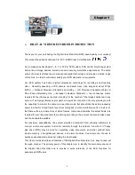
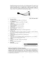
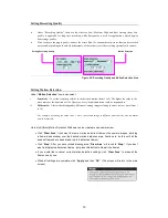
Use BNC pigtail adaptor to connect NTSC or PAL compatible cameras. See Figure1-3; the
position and numbering of the on-screen camera output is determined by the slot and channel
numbering sequence of the cards. For example, camera 1 would be connected to channel 1 of
card 1, camera 2 would be connected to channel 2 of card 1, camera 5 would be connected to
channel 1 of card 2, etc., since there are 4 available channels per card slot.
Figure 1-4: BNC pigtail adaptor
4.
Ethernet LAN Port
Use an RJ-45 LAN cable to connect to a LAN or Internet.
5.
VGA Display Port
This port is used to connect an external CRT or TFT display.
6.
Printer Port
This port is used to connect a printer to the DVR.
7.
PS/2 Keyboard Port
This port connects a PS/2 compatible keyboard.
8.
PS/2 Mouse Port
This port connects a PS/2 compatible mouse.
9.
Power Cord Socket
This socket is used to connect the power cord to the wall power outlet.
10.
Voltage Switch
The voltage switch regulates the voltage specifications of 110/220V, as required for different
regions. Switch the voltage according to your region’s requirements.
11.
Power Switch
Use this switch to power the machine on or to cut off the power.
12.
RS-232 Port
Connect this socket to the MODEM to enable the sending of alarm alerts, or to convert RS-232
to RS-485 devices to control the PTZ video camera.
13.
USB Port
This socket is used to connect USB devices for data output.
14.
Speaker
This is used to make the alarm sound.
15.
Microphone
This is used for sound input.
Preparing the Digital Video Recorder for Operation
To prepare your Digital Video Recorder for operation, you should first connect all peripheral devices.
Make sure the DVR is turned off before you do this. Once you have connected all peripheral devices,
check that the voltage switch is appropriate for your region (115/230). Make sure the floppy drive does
not contain a diskette, and there are no discs in the CD / CD-RW drive; if there are any discs, press the
eject button to eject an inserted disc.


