


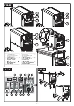

6.2WELDING WITHTHE SPOOL GUN
Fig. B,C
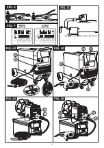
(Fig.N)
Important:
- Switch on the welding machine,
- Select the type of material, the type of gas and the wire diameter by pressing buttons
respectively.
- Set the welding current by means of the switch and rotary switch (if present)
.
- The display will show the welding current corresponding to the setting that has just
been made. Pressing button
will show the corresponding factory setting for the
wire feed rate (LED
DEFAULT on).
NOTE: ensure good welding results can be ensured by varying the wire feed rate
within a preset interval. This interval is indicated by LED
DEFAULT lighting up;
outside the DEFAULT interval the LED will go off.
- Select the welding mode by pressing button
.
- Press the torch button to start welding.
NOTE: during welding the display will show the actual value of the current.
- It is possible to modify the wire feed rate by adjusting the spool gun potentiometer,
and the display will instantly show the corresponding value; the current reading will
re-appear as soon as the adjustment has been completed.
for each position of the switch, the welding machine stores all the
parameters for the last welding job to be carried out (material, gas, wire diameter, wire
feed rate).
The DEFAULT values for the accessory welding parameters (slope up, burn-back time,
pre-gas time) are preset by the manufacturer; to customise each parameter proceed
as follows:
- Press button
for at least 3 seconds until the message “nor” appears on the display.
- Press button
until the LED (
or
or
) lights up for the corresponding
accessory parameter to be programmed.
Pressing buttons
and
simultaneously (not in programming mode) will restore all
welding parameters to their default values.
__________________________________________________________________
__________________________________________________________________
-
At the same time make sure the electrical connections are tight and check the
wiring for damage to the insulation.
-
At the end of these operations re-assemble the panels of the welding machine and
screw the fastening screws right down.
-
Never, ever carry out welding operations while the welding machine is open.
, ,
- Under critical welding conditions, the wire diameter LED will flash.
- Set spot welding operation by pressing button
- Press button
until LED
lights up. Use knob
to set spot duration.
- Press the torch or spool gun button and start welding. It will stop automatically after
the pre-set time.
-
See also
for directions relating to the procedure.
The thermostatic protection LED
lights up when there is overheating (also, the
display shows the message
) and cuts off the power supply; the system is reset
automatically after a few minutes' cooling.
-
Do not put the torch or its cable on hot pieces; this would cause the insulating
materials to melt, making the torch unusable after a very short time;
-
Make regular checks on the gas pipe and connector seals;
-
Every time the wire reel is changed, blow out the wire-guide hose using dry
compressed air (max. 5 bar) to make sure it is not damaged;
-
At least once a day, check the wear and correct assembly of the parts at the end of
the torch: nozzle, contact tip, gas diffuser.
-
Make frequent checks on the state of wear of the wire feeder rollers, regularly
remove the metal dust deposited in the feeder area (rollers and wire-guide infeed
and outfeed).
-
Inspect the welding machine regularly, with a frequency depending on use and the
dustiness of the environment, and remove the dust deposited on the transformer,
reactance and rectifier using a jet of dry compressed air (max. 10 bar).
-
Do not direct the jet of compressed air on the electronic boards; these can be
cleaned with a very soft brush or suitable solvents.
6.3 SPOTWELDING OPERATION
Fig. C
.
Fig. O
6.4 OVERLOAD PROTECTION
Fig. C
ALL thr
6.5 PROGRAMMINGTHEWELDING PARAMETERS
Fig. C
6.6 RESETTING ALL PARAMETERSTOTHE DEFAULTVALUES
Fig.C
WARNING! BEFORE CARRYING OUT MAINTENANCE OPERATIONS MAKE
SURETHE WELDING MACHINE IS SWITCHED OFF AND DISCONNECTED FROM
THE MAIN POWER SUPPLY.
7.1 ROUTINE MAINTENANCE:
ROUTINE MAINTENANCE OPERATIONS CAN BE CARRIED OUT BY THE
OPERATOR.
Torch
Wire feeder
7.2 EXTRAORDINARY MAINTENANCE:
EXTRAORDINARY MAINTENANCE OPERATIONS SHOULD BE CARRIED OUT
ONLY AND EXCLUSIVELY BY SKILLED OR AUTHORISED ELECTRICAL-
MECHANICALTECHNICIANS.
WARNING! BEFORE REMOVING THE WELDING MACHINE PANELS AND
WORKING INSIDE THE MACHINE MAKE SURE THE WELDING MACHINE IS
SWITCHED OFF AND DISCONNECTED FROM THE MAIN POWER SUPPLY
OUTLET.
If checks are made inside the welding machine while it is live, this may cause
serious electric shock due to direct contact with live parts and/or injury due to
direct contact with moving parts.
7. MAINTENANCE
- Turn knob
to modify the value of the selected parameter.
Adjustment range nor, r_1, ..., r_9 (nor = start without slope, r_1 = very quick start,
r_9 = very slow start).
Adjustment range 0-1sec.
Adjustment range 0-3sec.
- To restore the factory (default) setting press buttons
and
simultaneously for 3
seconds.
- To store the defined value and exit programming mode, press button
again for at
least 3 seconds.
Wire feed rate slope up:
Burn-back time:
Post-gas time:
- 13 -
Summary of Contents for PRO MIG 180
Page 28: ...FIG E FIG F 28...
Page 29: ...29...


