Lightmed LightLink-CXL Service Manual Download Page 46


LightLink-CXL – Service Manual  

                          Rev. No. :  01 

Page 

45

 of 

98


B.        LCD Power Supply  


This power supply converts the AC to DC voltage and provides the corrected voltage 
to the LCD display module.  It is an auto-ranging power supply module.   The input 
main voltage can be ranged from 90 to 240 AC volts.   The output voltage is +24 VDC. 
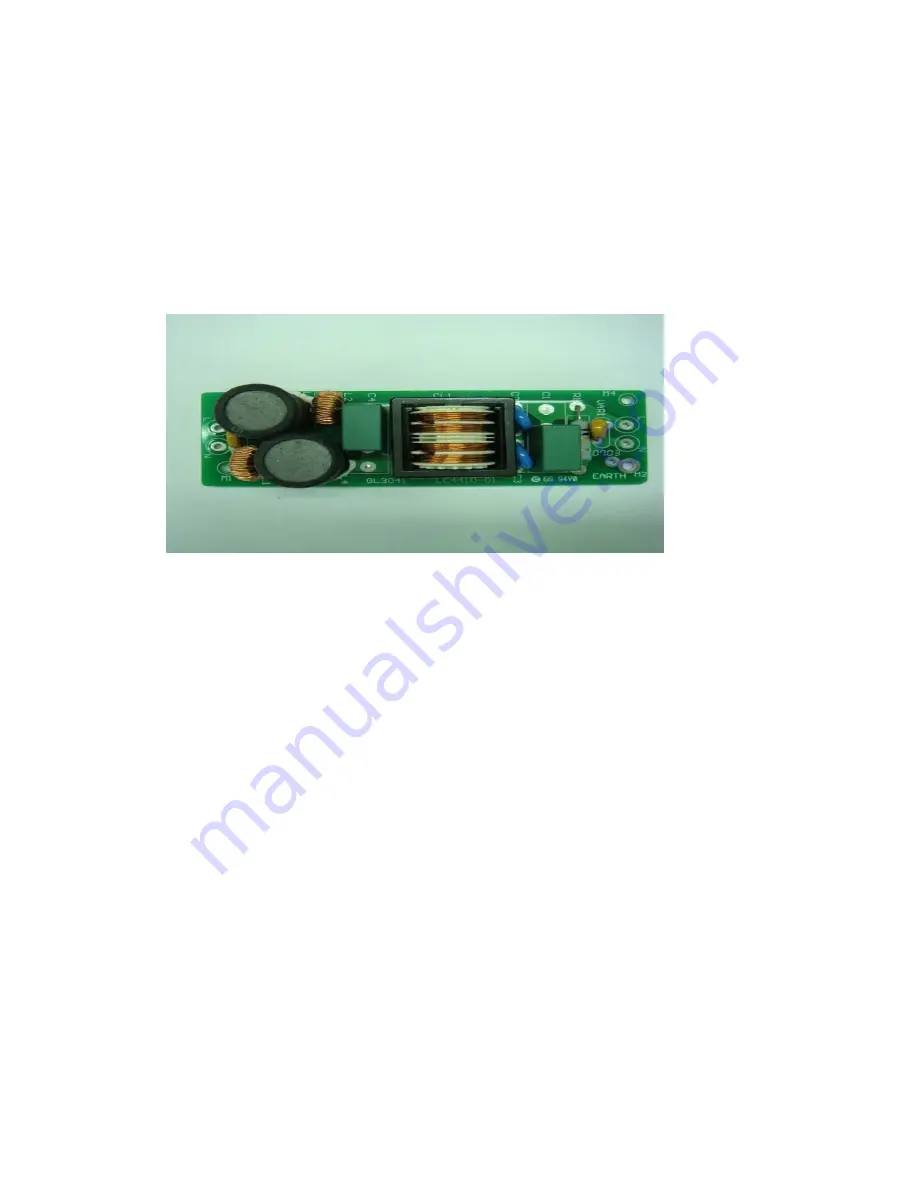
 

C.       AC Filter PCB  


Figure 5.11  AC filter PCB 

The Input mains voltage is connected to this PCB.  This PCB provides electrical 
filtering so that the Laser system can pass the EMC requirements of the relevant 
standards.  It is auto-switching range voltage. 


3.


LCD Interface Module 


This software platform provides an interface between the user and console system.    
More  screen  operation  control  are  detailed  or  explained  in  the  operator  manual 
section 4 on page 22. 


Summary of Contents for LightLink-CXL

Page 1: ...Service Manual LightLink CXL Corneal Cross Linking System ...

Page 2: ...Service Manual for the LightLink CXL Corneal Cross Linking System Directive 93 42 EEC as amended by 2007 47 EC Doc No DCX002 Rev No 01 ...

Page 3: ... radiation exposure CAUTIONS Any modification to the Ophthalmic Device will result in the necessity for it to be reclassified CAUTIONS U S law restricts this device to sell by or on the order of a physician This Service Manual contains confidential and proprietary information of the Manufacturer Manufactured by LightMed Corporation No 1 1 Ln 1 Pao An St Sec 3 Shulin District New Taipei City 23861 ...

Page 4: ...anual Rev No 01 Page 3 of 98 Document Title Preliminary Service Manual for the LightLink CXL Corneal Cross Linking System Document Number DCX002 Document Revision History DRAFT Sep 2012 Draft prepared 01 Aug 2014 New release ...

Page 5: ...ocess 20 4 6 Final Verification Checkout 30 Section 5 SYSTEM OVERVIEW 33 5 1 General Operating Theory 33 5 2 Theory of Operation 34 5 3 System Subassemblies 37 1 Laser Head Ass y 36 A CPU PCB 36 B Aiming Module 39 C CCD Camera 40 D Aperture Motor Ass y 41 E Backlight LED 42 F Detector PCB 43 2 Power control box 44 A Power Supply 44 B LCD Power Supply 45 C AC Filter PCB 45 3 LCD Interface Module 45...

Page 6: ...ty Adjustment 76 2 CCD Camera Alignment 79 Section 8 MAINTENANCE 81 8 1 Operator User Maintenance 81 8 2 Periodic Maintenance 81 8 3 Repairs 82 8 4 Periodic Maintenance 82 Section 9 TROUBLESHOOTING 83 9 1 Warning 83 9 2 Error Codes 84 Section 10 SOFTWARE UPGRADING PROCEDURES 86 10 1 Introduction 86 10 2 Preparation 836 10 3 Driver Software Downloading and Installation 836 10 4 Software Installatio...

Page 7: ...r arm ass y Assembling 24 4 12 Wiring Clearances and End Cap Assembling 24 4 13 Tray Table Assembling 25 4 14 Four Screws Removing Process 26 4 15 UV Head Holding 26 4 16 UV Head Holder Securing Porcess 27 4 17 UV Head Connection 28 4 18 The cabling twining laser arm ass y 28 4 19 Upper laser cover ass y 1 29 4 20 System is Ready 29 4 21 Treatment mode 31 5 1 System Block Diagram Overview 35 5 2 C...

Page 8: ...ocal Length 60 7 7 Origin Spot Size Calibration 61 7 8 5mm Spot Size Calibration 61 7 9 Wavelength Setup 62 7 10 Power Parameter Menu 62 7 11 UV Light in the Detector Area 63 7 12 Power Parameter 64 7 13 Detector Parameter Setup 66 7 14 Detector Trim Pot VR3 Adjustment Location 67 7 15 Detector Parameter 67 7 16 Power Spot Parameter 69 7 17 Aiming is not overlapping with UV Light 72 7 18 Aiming Al...

Page 9: ...o 01 Page 8 of 98 Record Sheet Installation Record Sheet 33 Power Parameter Calibration Record Sheet 65 Detector Parameter Calibration Record Sheet 68 Spot Size Power Calibration Record Sheet 70 Aiming Power Calibration Record Sheet 78 ...

Page 10: ... may be used in the LightLink CXL The Manufacturer and Distribution organization shall not be held liable or responsible for damages or injury caused as a result of using non approved accessories All maintenance and service work must be carried out by authorized and trained service agents and only those procedures outlined in the operator and service manual are allowed Any service work carried out...

Page 11: ... of the entire protocol on how to use the equipment its prescription and application in a particular patient as well as ministering the dosage of photosensitive drugs applied to the patient The ultraviolet photosensitive drug is not an integral part of the LightLink CXL Corneal Cross Linking System Its acquisition storage and handling are the user responsibility The ultraviolet photosensitive drug...

Page 12: ...erformed by qualified professionals approved by LightMed Corporation For safety reasons unauthorized persons should never open the equipment therefore avoiding dangerous situations Always use clinical protocols that are scientifically recognized nationally or internationally The equipment s correct functioning depends on the installation in addition to a suitable location selected for its operatio...

Page 13: ...anufacturer 2 3 User Safety The LightLink CXL Corneal Cross Linking System is electro medical equipment emitting ultraviolet light developed in accordance with the International Standards for Safety For the type of equipment that emits ultraviolet light it is recommended to avoid exposure of skin and eyes to the light beam if no therapy is being performed The operators must be aware that they cann...

Page 14: ...his equipment and the user is accountable for taking all the precautions listed 2 4 Patient Safety The LightLink CXL Corneal Cross Linking System should be operated by an Ophthalmologist who has knowledge about the Corneal Crosslink treatment and the methods for using this equipment The patient must be lying down on a stretcher or comfortable reclining bed in a calm atmosphere that does not create...

Page 15: ...RFACE 11 6 Touch screen colour LCD with built in PC PULSE DURATION Adjustable 10S 30min CALIBRATION Automatic INTEGRATED POWER METER YES MAX POWER OUTPUT ERROR 10 SPOT SIZES 4 11mm Continuously Variable WORKING DISTANCE 120 mm AIMING BEAM Dual Red Diodes 635 650nm AIMING BEAM POWER 1 0mW VIDEO SYSTEM Integrated Hi Res Auto Focusing Camera FLOOR STAND Integrated height adjustable with pantographic ...

Page 16: ...sport 500 1060 mbar Cooling System Air cooled Optional Accessories The following accessory can be purchased from the Distributor to use with LightLink CXL Corneal Cross Linking System UV light Product It is only available for customers outside the EU Countries due to the requirements for CE Marking The manufacturer does not have controlled over the use of the attachments that are available and the...

Page 17: ...he installation requirements are 1 100 230 Volts 50 or 60Hz AC mains power supply with an earth connection This is a single phase outlet capable of delivering up to 400 Watts 2 A mains power cable is supplied but the connector may not suit the outlet available so it is advisable to have a spare locally compatible cable available The Cable assembly must be CE approved for EU Countries 3 A suitable ...

Page 18: ...s Operator Manual 4 2 Unpacking and Receiving Inspection When receiving the UV light system usually there is only one cardboard box Inside the box you will receive the wheel base control box LCD touch screen UV light head and UV light arm ass y Figure 4 1 Whole System Packaging Carton XL0000 LightLink CXL Serial Number Manufactured By LightMed Corporation No 1 1 Lane 1 Pao An St Sec 3 Shulin City ...

Page 19: ...sed to confirm the individual layer contents and notify the manufacturer if any discrepancy The motorized table is an optional and may be purchased from the manufacturer 4 3 Tools and Equipment In order to be able to effectively carry out a full initial installation of the LightLink CXL Corneal Cross Linking System the following tools and equipment are required and available from the manufacturer ...

Page 20: ...pect for any transportation damage and general condition Extreme care do not to touch the optic lens or parts and make sure all the items are available The System consist of four major parts as follows Base wheel Control box LCD Touch Screen Swing UV Arm UV light Head Figure 4 3 LightLink CXL Corneal Cross Linking System Breakdown UV light Head UV light Arm LCD Touch Screen Base Wheel Control Box ...

Page 21: ...g process appropriate tools installation site selection and environment precaution are prepared Please follows the below procedures Roll out the base wheel control box and station it over well level ground Lock up the wheel station two stoppers refer to fig 4 4 Figure 4 4 Wheel Stopper Location Wheel stopper ...

Page 22: ...e LCD display ass y with the bracket mounted and gently release or pull the releasing latch outward or backward refer to figure below Figure 4 5 LCD Ass y latching releasing process 1 Figure 4 6 LCD Ass y latching releasing process 2 Latch head pulling backward ...

Page 23: ... Rev No 01 Page 22 of 98 Take released latch LCD and gently slide against the mounting bracket and lock the latch when it is through Figure 4 7 LCD Ass y latching process 1 Figure 4 8 LCD Ass y latching process 2 Mounting Bracket ...

Page 24: ... securing the screw and 9 pins connector needs to be connected at COM Port Figure 4 9 LCD cable connecting process Release the pressurized button to lift up height Note By doing this process will allow the arm ass y and base wheel ass y are closer and easily to slide in the arm ass y Figure 4 10 Elevation Process Pressurized button ...

Page 25: ... hold and connect the connector Note Ensure the wheel base is locked all the time before the arm ass y is mounting Figure 4 11 Laser Arm Ass y Assembling Gently glide in over the wheel base and ensure the no tangle or jam in the wiring Figure 4 12 Wiring Clearances and End Cap Assembling Cover the cap ...

Page 26: ...en or loosen wiring during the arm swinging process Place the end cap after the wiring clearance process is completed it Take the tray table top and gently slide over the base and secure with the two screws Note The height can be determine on the user preference but once secured the tray top will remain the adjusted height and can t longer adjustable until it reset it again Figure 4 13 Tray Table ...

Page 27: ...ently place UV head into holder then set stopper locker at under side Figure 4 14 Four Screws Removing Process Figure 4 15 UV head Holding Note Do not let goes of holder before securing the UV holder Leave this side hanging over the laser arm Leave this side hanging over the laser arm Four Screws Removing ...

Page 28: ...e laser with four screws Note Be extreme careful about securing the laser head if you are installing alone due to improper installation will result laser head dropping Ensure the stopper is always locked prior for any swing integrity test Figure 4 16 UV Head Holder Securing Process Stopper lock Always at lower position ...

Page 29: ... the cabling is CW winding only and connect the connector red dot to red dot Figure 4 17 UV Head Connection Take the two upper laser cover ass y and gently assemble over the laser arm with four screws Figure 4 19 Upper Laser Cover Assembling Red dot to red dot ...

Page 30: ...LightLink CXL Service Manual Rev No 01 Page 29 of 98 Now the system is fully installed and ready to initial the testing Figure 4 20 System is Ready ...

Page 31: ...ing section 8 0 If the system rechecking process is valid then the system is ready to go More detailed screen operation and description refer to section 4 2 page 21 Now the system is fully setup the final verification is required to conduct before demo or handle over to user end These performance procedures can be divided as follows UPS Main power rechecks Optional LCD Software and camera rechecks...

Page 32: ...ion System Initialization and Validation Once everything validated then proceed to system initialization process A Control Panel Integrity Randomly select the treat mode Validate if there is communication protocol establish Validate all the controls are functioning accordingly such as aiming intensity Backlight etc Execute the UV process B Aiming Integrity Validation Engage the aiming intensity to...

Page 33: ...tem assembly 2 UV light System Checks 2 1 UV light Power ON is indicated by Display LEDs being ON 2 2 UV light System does self checks at Start up 2 3 Confirm that no Error messages are displayed 2 4 All Display Panel controls and displays are functioning 2 5 The Aiming beam is visible and intensity is adjustable Installers Name _____________________ Date __________________ Distributor Name ______...

Page 34: ...clinically referred to as Corneal Cross linking The system consists of three major parts Laser Head Control Box and LCD touch control panel integrated with computer platform A coil power cord is uncoiled and connected to appropriate source power plug in order for system to function properly first Secondly power switch on the LCD control panel display is then turn on and wait for the system to boot...

Page 35: ...ed and distributed It includes MCU PCB laser rod two aiming modules CCD camera aperture motor and backlight LED More detailed descriptions are explained in the System Component section Control Box Ass y It consists of AC filter PCB Power supply LCD power source and UPS optional For more detailed individual component are explained in the system component section LCD Control Panel Ass y It provides ...

Page 36: ...sign of the Crosslink system These blocks diagram includes PC UI controller Power supply and CPU Module For details individual subassemblies or components explanation are listed below Figure 5 1 System Block Diagram Overview Micro Controller Interlock Aiming Diode 365 UV LED LED Lamp Power Supply AC Mains PC Controller Motor Controller Power Supply Webcam UV LED Detector ...

Page 37: ...N8 4 Aiming Module Signal Connector CN4 5 Aiming Module Signal Connector CN5 6 Interlock Key Connector CN6 7 Aiming Intensity VR1 8 Aiming Intensity VR2 9 Aperture Motor VR Connector CN7 10 RS232 Communication Connector CN3 11 Aperture Motor Connector CN9 12 Power Energy Gain Adjuster VR3 13 Software Download Connector JP1 14 CPU Chips U1 15 Buzzer BZ1 Figure 5 3 Legends 15 14 13 12 11 10 9 8 7 1 ...

Page 38: ...ow 16 VDC then the laser is in OFF condition This is triggering system is accomplished by Schmitt trigger concept The CPU then will translate if the voltage is at 5VDC for ON or 20VDC state and 0 VDC for OFF or 16VDC state and it can measure across the TP17 POR signal If the laser is unable to function properly or has no output then confirm if there is 24 VDC across the ZD1 or CN1 connector or TP1...

Page 39: ... circuitry loop Two aiming intensity can be adjusted through VR1 and VR2 pot CN4 connector is corresponding to VR1 and CN5 is VR2 Aiming control voltage range is from 0 to 2 5VDC and can measure across TP9 Laser aperture controlled circuit is controlled by VR via CN7 connection The VR value determines the aperture size where then translate the motor position through LM628 motor controlled IC The m...

Page 40: ... modules Left side Two aiming modules are used to aim the target The intensity can be recalibrated in the CPU PCB through two VRs VR1 and VR2 The intensity is range from 0 to 600 mW The voltage is proportional to intensity The intensity is divided into 10 segment bar graph Aiming NO 1 Right Aiming NO 2 Left ...

Page 41: ...he treatment area closely and accurately The resolution of the camera is 1200 million pixels CCD camera is USB plug in device and the applied voltage is 5VDC and the current consumption is 0 5A The CCD camera position can be realigned through the four set screws More detailed you may refer to the realignment process on page 79 CCD camera ...

Page 42: ...his motor ass y is used to control the laser aperture spot size The VR pot is reflected back the DAC position for CPU to control The motor applied voltage is 12VDC The motor ass y has current limited protection of 60 mA so if there is any over current incident the system will shut it down Aperture Motor Ass y ...

Page 43: ...ight LEDs Figure 5 8 Backlight LED Ass y This white backlight LED is used to assist the doctor to see the treatment area much more clearly The applied voltage is 12 VDC The LED intensity is driven by current The max current limitation is 40mA White LED Backlight ...

Page 44: ...ual Rev No 01 Page 43 of 98 F Detector PCB Figure 5 9 Detector Ass y This detector is used to feedback the laser output power to MCU so it will recalculate if the power gain is correctly The applied voltage is 5VDC Detector PCB ...

Page 45: ... box A Power Supply This power supply converts the AC to DC voltage and provides the corrected voltage to operate system It is an auto ranging power supply module The input main voltage can be ranged from 90 to 240 AC volts The output voltage is 12 VDC Power Supply LCD Power Supply AC Filtering PCB ...

Page 46: ...lts The output voltage is 24 VDC C AC Filter PCB Figure 5 11 AC filter PCB The Input mains voltage is connected to this PCB This PCB provides electrical filtering so that the Laser system can pass the EMC requirements of the relevant standards It is auto switching range voltage 3 LCD Interface Module This software platform provides an interface between the user and console system More screen opera...

Page 47: ...ystem Before performing any of these repair procedures be sure you have used the troubleshooting procedures in Section 9 of this manual to properly isolate the instrument s problems Repair Notes Before removing any module part ensure the power is always turned off and power cord disconnected Ensure the statics wrist band is always worn prior to removing any laser diodes since they are static sensi...

Page 48: ...val 1 Remove the laser head cover off only the front cover 2 Disconnect and tag the cablings or connectors 3 Remove the three screws by using 2 0mm Allen key 4 Gently and slowly remove the PCB down Note Do remember to tag all the connectors Figure 6 1 UV head PCB Other two screws First screw ...

Page 49: ...ng at the back of PCB Installation 1 Reseat the PCB back to the screw pole and screws back the three screws 2 Reconnect all the connectors and verify them carefully prior to power on Note Do remember to reconnect all connectors before turning on the power 3 Ensure there is no loosen connections and close up the cover top 4 Power on and validate the system performance refer to section 4 6 on page 3...

Page 50: ...f both the front and rear cover 2 Disconnect the aiming connector Depending on the which one 3 Loosen the screw by using 3 0 mm Allen key 4 Gently and slowly remove the laser diode and holder Note Do remember to tag all the connectors Figure 6 3 Aiming set screw Figure 6 4 Aiming connectors Two aiming connectors Set screw ...

Page 51: ...e set screw 2 Reconnect the connectors and verify it carefully prior to power on Note Do remember to reconnect the connector before turning on the power 3 Ensure there is no loosen connections and close up the cover top 4 Power on and validate the system performance and recalibrate it if required refer to section 7 on page 72 ...

Page 52: ...ve the PCB down Figure 6 5 Detector PCB replacement Installation 1 Reseat the PCB back and screw back the two screws 2 Reconnect back the connector 3 Reseat the CPU PCB back to the screw pole and screws back the three screws 4 Reconnect all the connectors and verify them carefully prior to power on Note Do remember to reconnect all connectors before turning on the power 5 Ensure there is no loosen...

Page 53: ...the connectors 5 Loosen the two screws and take Backlight PCB off Remember disconnect Figure 6 6 Backlight PCB Replacement Installation 1 Reseat the PCB back to the screw pole and screws back the three screws 2 Reconnect all the connectors and verify them carefully prior to power on Note Do remember to reconnect all connectors before turning on the power 3 Ensure there is no loosen connections and...

Page 54: ...Loosen all the screws and gently remove the motor ass y from the gear contact Figure 6 7 Aperture Motor Ass y Replacement Installation 1 Reseat the motor ass y back to the gear and screws back the screws 2 Reseat the CPU PCB ass y back 3 Reconnect all the connectors and verify them carefully prior to power on Note Do remember to reconnect all connectors before turning on the power 4 Ensure there i...

Page 55: ...and tag the cablings or connectors 3 Remove the three screws 4 Gently and slowly remove the PCB down Note Do remember to tag all the connectors 5 Loosen two screws and take CCD and holder off 6 Loosen nut at front side and take connect off Note This step must take all the connector off in addition to aiming connector Figure 6 8 CCD Camera Replacement Two screws and wirings ...

Page 56: ...ack and use two screws lock it 3 Reseat the PCB back to the screw pole and screws back the three screws 4 Reconnect all the connectors and verify them carefully prior to power on Note Do remember to reconnect all connectors before turning on the power 5 Ensure there is no loosen connections and close up the cover 6 Power on and validate the system performance refer to section 7 on page 79 Holder N...

Page 57: ...d to conduct this process Performing these procedures will reset the all the factors of the laser system The procedures can be defined into four parts Motor Aperture Calibration Motor Parameter Power Calibration Power Parameter Detector Calibration Detector Parameter Spot Size Power Calibration Power Spot Parameter Equipments Tools required Interlock Connector Calibrated Laser Power Meter Safety G...

Page 58: ...ny treatment procedure Improper spot size will affect the treatment quality Access to calibration mode Double clicks the hidden icon at the left top corner screen refer to fig 7 1 Enter the pass code 0000 Figure 7 1 Pass code entering Restart the main program again by click the software program in startup menu Figure 7 2 The software position in Main Program Hidden Icon Pass code 0000 Double click...

Page 59: ...ing the main program Note If not striking the hidden icon correctly the all process will need to restart again Figure 7 3 A hidden icon at the left top corner on screen Figure 7 4 Main page of Calibration Mode Press the Motor Parameter icon to initial the calibration process Motor Parameter Icon Double clicks Hidden Icon ...

Page 60: ... Manual Rev No 01 Page 59 of 98 Set the spot size to 4mm and power to 1 mW Figure 7 5 Motor Aperture Calibration Motor Parameter Mode Start up the UV light execution run icon Power and Spot Configuration UV Light Run Button ...

Page 61: ...Rev No 01 Page 60 of 98 Raise or lower the laser head to focus the spot size and well homogeneous or spot intensity well distributed on the standard spot sizes calibration sheet Figure 7 6 UV Light At Focal Length Stop the UV light ...

Page 62: ...the process until it fits into the reference spot circle and save the calibration value and cycle power and validate the origin position or 4mm Repeat the same process from 5mm to 11mm and save every interval position value Note The position alignment from 5mm or above spot size is only in CW direction Figure 7 8 5mm Spot Size Calibration Origin Calibration Icon Saving Icon Motor Position Directio...

Page 63: ... Double clicks the hidden icon at the left top corner screen refer to Figure 7 1 Press the Power Parameter icon to initial the calibration process Set the power meter wavelength at 365 nm and set the spot size to 11mm in main calibration menu refer to motor parameter and power to 30 mW Initial Ready button for spot size reinitialization or reconfiguration process before entering the Power Paramete...

Page 64: ...Service Manual Rev No 01 Page 63 of 98 Place the Power meter underneath of laser head Note Ensure the spot size is centered of the detector area Figure 7 11 UV Light in the Detector Area Centered of the detector area ...

Page 65: ...ameter Measure the power against the calibration data sheet refer to below figure and adjust the factor value until it is consisted with the data sheet specification Repeat the same process until every scale is performed and calibrated Save the values before exiting from the power parameter screen Execution Run Key ...

Page 66: ...Power Interval Spot Size Standard Output Power Power Meter Readout Power Factor Pass V Fail X 1 45mW 11mm 42 8mW 20 2 30mW 11mm 28 5 mW 20 3 24mW 11mm 22 8mW 20 4 21mW 11mm 19 9mW 20 5 18mW 11mm 17 1mW 20 6 15mW 11mm 14 3mW 20 7 12mW 11mm 11 4mW 20 8 9mW 11mm 8 5mW 20 9 6mW 11mm 5 7mW 20 10 3mW 11mm 2 8mW 20 11 2mW 11mm 1 9mW 20 12 1mW 11mm 0 9mW 20 ...

Page 67: ...cedure Improper detected will result in treatment quality or endanger patience Enter to calibration mode Press the Detector Parameter icon to initial the calibration process Set the power meter wavelength at 365nm Refer to fig 7 9 and set the spot size to 11mm in main calibration menu refer to motor parameter and power to 30 mW Figure 7 13 Detector Parameter Setup Set Power at 30mW Set this factor...

Page 68: ...e UV light execution run icon Measure the detected value should fall within 28 5 20 for the 30mW interval Calibrate the VR3 if the range does meet the specification and repeat the same process once the value is within criteria refer to Figure 7 14 Figure 7 14 Detector Trim Pot VR3 Adjustment Location Proceed to next interval and adjust the interval ratio value so it will fall within the calibratio...

Page 69: ...val Spot Size Standard Output Power Power Meter Readout Detected VAL Readout Detector Factor Pass V Fail X 1 45mW 11mm 42 8mW 20 2 30mW 11mm 28 5 mW 20 3 24mW 11mm 22 8mW 20 4 21mW 11mm 19 9mW 20 5 18mW 11mm 17 1mW 20 6 15mW 11mm 14 3mW 20 7 12mW 11mm 11 4mW 20 8 9mW 11mm 8 5mW 20 9 6mW 11mm 5 7mW 20 10 3mW 11mm 2 8mW 20 11 2mW 11mm 1 9mW 20 12 1mW 11mm 0 9mW 20 ...

Page 70: ...cy during the treatment procedure Enter to calibration mode Press the Power Spot Parameter icon to initial the calibration process Set the power meter wavelength at 365nm and set the spot size to 11mm in main calibration menu refer to motor parameter and power to 30 mW Start UV light run icon and measure if the value falls within the calibration specification guideline Refer to below figure Figure...

Page 71: ...er Detector Performed by Dated Item Power Interval Spot Size Standard Output Power Power Meter Readout Spot Size Factor Pass V Fail X 1 45mW 11mm 42 8mW 20 2 45mW 10mm 35 3 mW 20 3 45mW 9mm 28 6mW 20 4 45mW 8mm 22 6mW 20 5 45mW 7mm 17 3mW 20 6 45mW 6mm 12 7mW 20 7 45mW 5mm 8 8mW 20 8 45mW 4mm 5 7mW 20 ...

Page 72: ...tine checkout process Prior to the commencing the procedure only the qualified personnel is permitted to conduct this process There are two alignments required when replacing 1 Aiming Alignment Intensity Overlapping 2 CCD Camera Alignment Equipments Tools required Interlock Connector Calibrated Laser Power Meter Safety Goggle 365nm wavelength VR pot adjuster or small flat screw driver Allen key 2 ...

Page 73: ...laser aperture or head Fire the UV and focus the spot size into homogeneously or well uniform Notice the distance between UV head and calibration sheet is focus distance Refer to section 7 motor aperture calibration page 55 Repeat the process until it is uniform and then off the UV light Use 2 0mm allen key and move the one spot toward to the reference spot size of 4mm Figure 7 17 Aiming is not ov...

Page 74: ...LightLink CXL Service Manual Rev No 01 Page 73 of 98 Use four screws on holder to move aiming beam to 4 mm spot size Figure 7 18 Aiming Alignment Screws Aiming Alignment Screws Location ...

Page 75: ...LightLink CXL Service Manual Rev No 01 Page 74 of 98 Repeat the same process until it is properly unifying at 4mm spot size and overlap with UV light Figure 7 19 Aiming overlapping with UV Light ...

Page 76: ... Open up the front laser cover ass y Enter calibration mode Initial the UV light and disengaged it Raise or lower the laser head for the aiming spots separation Figure 7 20 Separating Aiming Change aiming intensity to scale of 10 the largest power Figure 7 21 Aiming Energy Change to 10 ...

Page 77: ...tLink CXL Service Manual Rev No 01 Page 76 of 98 Set power meter wavelength at 650 nm Refer to page 61 power calibration Place the detector at one of the aiming spot Figure 7 22 One aiming spot in detector ...

Page 78: ...ow figure Figure 7 23 VR Location For Aiming Energy Repeat the same process until the value is reached Aiming Power Calibration Record Sheet System SN Power Meter Detector Performed by Dated Item Aiming A Intensity Scale Output A Power Power Meter Readout Aiming B Intensity Scale Output B Power Power Meter Readout 1 10 425 475μW 10 425 475μW 2 1 25 75μW 1 25 75μW Two VR control aiming energy ...

Page 79: ...n raise or lower UV head to let two aiming beam overlap Figure 7 24 CCD Camera with Aiming on the screen Gently pull back the rear laser cover ass y until you see the camera ass y Use 2 0 mm allen key to adjust the four screws at CCD holder and you will see aiming spots move toward center of the display Figure 7 25 CCD Camera alignment screen and Screws ...

Page 80: ...LightLink CXL Service Manual Rev No 01 Page 79 of 98 Move aiming light until it is near at the center of the screen Figure 7 26 CCD Camera alignment completion ...

Page 81: ...re urged to contact the authorized representative or the manufacturer in order to decide on a suitable course of action Refer to Section 9 of this Manual for particular National requirements of EU Countries 8 1 Operator User Maintenance It is recommended that the LightLink CXL Corneal Cross Linking System equipment is annually checked by LightMed Authorized Representative Please contact the Author...

Page 82: ...ter cleaning the device wait at least 1 minute before plugging the LightLink CXL to the electrical outlet The LightLink CXL is a high precision equipment and so it is absolutely necessary that all possible care is taken during cleaning 8 3 Repairs To ensure a long and useful life to your medical equipment LightMed recommends that the LightMed Authorized Service distributor or your Technical Assist...

Page 83: ...g Cause s Remedy Action s Warning Interlock Interlock plug not connected Check the Interlock connection If the problem persists call the authorized service or manufacturer for further assistance Warning Motor Move Motor is moving Wait for Motor to be ready If the problem persists call the authorized service or manufacturer for further assistance Warning Communication failure Laser head power not e...

Page 84: ...or Failure Motor failed to operate Reboot the system If the problem persisted call the authorized service or manufacturer for further assistance Err 02 UV Diode Current Too High UV Diode current is out of range or over the limits Call the authorized service or manufacturer for further assistance Err 03 Aiming UV light Failure Aiming UV light beam failure Call the authorized service or manufacturer...

Page 85: ...zed service or manufacturer for further assistance Err 10 Watchdog Error System watchdog flag Reboot the system Call the authorized service or manufacturer for further assistance Err 11 Communication Error No communication between optical driver and the console within the time of frame of 300ms during UV firing Reboot the system If the problem persisted call the authorized service or manufacturer ...

Page 86: ...tem 10 2 Preparations Equipment Requirement MSP FET430UIF kit including MSP430 CD ROM MSP FET430UIF USB to JTAG Emulation Interface USB cable type A B 14 conductor cable PC or Laptop System Requirement Window XP or above 10 3 Driver Software Downloading Procedures Access the website http www elprotronic com download html and download the CSO14x01 or Flash Programmers for TI s MSP430 MCU uses TI s ...

Page 87: ...LightLink CXL Service Manual Rev No 01 Page 86 of 98 Execute the downloading process Wait till the process finished it ...

Page 88: ...LightLink CXL Service Manual Rev No 01 Page 87 of 98 Unzip the file 10 4 Software Installation Procedures A Window 7 version or above Execute the Setup file and Click the I agree term ...

Page 89: ...LightLink CXL Service Manual Rev No 01 Page 88 of 98 Step through all below procedures until the installation completed it ...

Page 90: ...LightLink CXL Service Manual Rev No 01 Page 89 of 98 ...

Page 91: ...LightLink CXL Service Manual Rev No 01 Page 90 of 98 ...

Page 92: ...l Rev No 01 Page 91 of 98 B Window XP Version Execute the Setup file and Click the I agree term Step through all below figures Configure the path to be C Program Files IAR Systems Embedded Workbench 4 0 430 drivers TIUSBFET WinXP ...

Page 93: ...LightLink CXL Service Manual Rev No 01 Page 92 of 98 ...

Page 94: ...Manual Rev No 01 Page 93 of 98 10 5 Configuration Procedures Plug in the MSP FET430UIF including the cable and execute the program icon Click the Setup menu and open up the Memory Option Ensure below configuration are set up ...

Page 95: ...htLink CXL Service Manual Rev No 01 Page 94 of 98 Open up the Setup menu and then Connection Device Reset Validate if the below configuration are set up correctly End of configuration and exit the program ...

Page 96: ...nt cover and locate the MCU socket and then plug in Power on the head and configure the download file by Open Code File icon Retrieve the file MCU from your destination or stored area Choose the microcontroller group to be MSP430F1xx and MSP430F169 Execute AUTO PROG icon for the downloading process begins Programming initialization Group Selection Specific type selection File retrieving MCU ...

Page 97: ...LightLink CXL Service Manual Rev No 01 Page 96 of 98 Finish this process we will get PASS ...

Page 98: ... not serviced according to the instructions and procedures contained in the manual is subjected to misuse negligence or accidents is not installed according to the manufacturer instructions is connected to or used with accessories or spare parts that are not and have not been tested and approved by the Manufacturer The obligation of this warranty shall be limited to the repair or replacement at th...

Page 99: ...LightLink CXL Service Manual Rev No 01 Page 98 of 98 ...

Reviews: