background image

12 


8.


Exchanging components 


8.1.


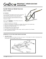
Exchanging/Removing the covers 


The covers are attached with  screws, 
clips and velcro. 

To  remove  the  collateral  covers, 
unscrew  (A,B)  at  the  front  on  the 

inside  and  at  the  rear  first,  and  then 
take the cover upwards to remove it. 

To  remove  the  rear  cover,  lift  the 

cover  at  rear  bottom  and  take  it  off 
the Velcro, now you can lift the cover 

upwards to remove it.  
If  your  wheelchair  is  equipped  with 

light, you have to unplug the lights as 
well to remove the cover. 

Summary of Contents for C3

Page 1: ...e instructions before servicing the wheelchair This service manual must be read in conjunction with the user manual Alterations in constructional and technical manner or to the electronic require the written authorisation of LEVO Ltd otherwise no warranty or product liability will be accepted Version 1 9 ...

Page 2: ...hanging the middle wheel 14 8 4 Exchanging the front wheel 14 8 5 Exchanging the back rotatable wheel 14 8 6 Exchanging the rear caster 15 8 7 Exchange the front wheel lowering cable 15 8 8 Gas spring exchange for tilt in space 18 8 9 Moving the seat to the front or back 18 8 10 Exchanging the brake release cable 18 8 11 Exchanging the drive motor 19 8 12 Tightening the drive chain 19 8 13 Exchang...

Page 3: ... 24 How to get battery access without power 34 9 Function control 34 10 Cleaning 34 11 Technical information 35 11 1 General information 35 11 2 Measurements metric 36 11 3 Measurements british 37 11 4 Electromagnetic Interference EMI 38 12 Controller self help guide VR 2 39 13 Controller self help guide R net 40 14 Battery Wiring 40 15 Version Management 41 ...

Page 4: ...r appreciates the safety and the reliability of a well maintained wheelchair This manual must always be read and used with the user manual 2 Health safety Accidents do occur When working on or testing the wheelchair be aware of the dangers and take care to ensure your own and other peoples health and safety 3 Adjustments The majority of the adjustments can be carried out by the user or their famil...

Page 5: ...essionals with in depth knowledge of PG Drives electronic control systems Incorrect programming could result in an unsafe set up of a wheelchair for the user LEVO AG accepts no liability for losses of any kind if the drive or stability characteristics of the wheelchair are altered without prior notification and discussion with LEVO AG It is in the responsibility of the person programming the contr...

Page 6: ...of speed and driving settings in the chair for both indoor and outdoor use Because multiple profiles per ordered speed setting are used you do not need to make the choice for the Standard Classic and Fun at the order form anymore Motor setting improvements To optimize the current through the motors when they are pushed to their limits we have improved some parameters in the motor settings section ...

Page 7: ... your local LEVO agent Addresses are given at the front of this service manual Major repairs For all major repairs e g bent or damaged frame always replace complete components Never try to repair damaged steel work or components Replacement parts Factory replacement components should be used in all repairs these are available from LEVO AG To order parts see the parts list drawings and the correlat...

Page 8: ...d screwdriver and slotted screwdriver Soft headed hammer Torque settings Bolt size Torque Nm M4 3 M5 6 M6 10 M8 25 M10 50 6 Important points Do not reuse locknuts Always replace with a new locknut Always use thread locking compound Always use recommended components and parts available from LEVO AG Do not modify or repair the frame LEVO is responsible for repairs on gas springs motors and electroni...

Page 9: ...loth for cleaning Tires must get replaced when the tire s profile is worn down For more information please consult sector 8 3 to 8 5 Check the free wheel device and the motor disengaging lever for correct operation Repair any fault found Check the mechanical function of the motor disengaging lever Pull the quick release bolt out and press the motor disengaging lever downwards Now you should be abl...

Page 10: ... middle wheel must be lifted up in standing configuration Use all functions and drive the wheelchair as a final check In case you notice any kind of problems arrange final repairs 7 1 Brake Test These tests should be carried out on a level floor with at least one meter clear space around the wheelchair Switch on the control system Check the display remains on or flashes slowly after one second Pus...

Page 11: ...the wheelchair and reverse down the gradient While on the gradient release the joystick and ensure the wheelchair comes to rest and the brakes are applied 7 4 Lubrication There is no need to lubricate the moving parts and the joints on the chair There are 3 exceptions At the conversion support if the chair is equipped with option tilt in space it is necessary to put on some grease once a year At t...

Page 12: ...vers unscrew A B at the front on the inside and at the rear first and then take the cover upwards to remove it To remove the rear cover lift the cover at rear bottom and take it off the Velcro now you can lift the cover upwards to remove it If your wheelchair is equipped with light you have to unplug the lights as well to remove the cover A B ...

Page 13: ...k wise the shock absorber gets shorter less front wheels to floor clearance Rotating clock wise will extend the absorber more front wheels to floor clearance If more clearance is requested than you can reach the cable tension either on the front or the back end of the cable must be loosened The cable ends in the support which is attached at the end tube The cable tension has to be adjusted in sitt...

Page 14: ...t wheels are lifted off the ground Remove the cover cap in the middle of the wheel lift the cap with a small screwdriver Then loosen the screw and take off the wheel To fit the new wheel mount the parts in the reverse order use thread locker to mount the screw Remove the cover cap in the middle of the 7 twin wheel by using a fine screw driver to lift the cover cap off do that with both wheels Unsc...

Page 15: ...able support Take off the cable assembly E Dismount the front cover G loosening the screws F Release the metal ear M which holds the head of the front end cable H and take off the cable head Loosen the screw of the cable hose tension adjustment I and bring it off the holder K through the open gap L The whole cable assembly can now be replaced Assure that you line up the cable hose the same Reassem...

Page 16: ...16 The routing is beneath the design tubes The routing is above the light and indicator support The deviation starts from this point The cable will be routed through the chassis above the cross ...

Page 17: ... unit respectively attached at the levers of the Rosta element Important Cable Tension The cable tension has to be adjusted Due the nut underneath the support in sitting position and only must be light or soft so that the cable is nearly straight Further details on the spare part list ...

Page 18: ...e getting through and fasten the clasp screw A of the cylinder head D again If you now use the brake release lever you should hear a click in the middle of the braking distance If this is not the case adjust the tension of the cable by adjusting the cylinder head D Unscrew the 4 screws A and then slide the seat back or forth When you reach the required position put the screws back in and tighten t...

Page 19: ...he tension of the drive chain you can remove the rubber cover cap between the front wheel and the middle wheel To adjust the tension loosen grub screw A Take two metal bolts and place them in the two holes B push a screw driver between the two bolts and turn the excentric around the chain to tighten or loosen it When you reach the wished tension tighten the grub screw again Unscrew the screw A bel...

Page 20: ... 8 21 Remove all cable cords from the joystick cable all the way down to the seat pan and unthread the cable Unscrew both screws A under the joystick now you can replace the joystick module Fasten the module again with both screws on the joystick holder thread the joystick cable and plug it in and fasten it with cable binder on to the armrest to the back and under the seat Remove the back cover in...

Page 21: ...ed by a tightening system If the chair is more in standing position secure it over the seat front side If the chair is more in seating position secure it at the back Take off and unplug the battery cover To improve the access to the retrofit area bring the seat system into full tilt position Disassemble the knee support the foot rest the cover of the leg rest assembly and the cushion The speed lim...

Page 22: ...g actuator in standing position CAUTION During movements assure nobody has their fingers or hands inside the seating system or main frame If the chair is more in standing position secure it over the seat front side or by an assistance which may help Loose the coupling bolt at the base underneath the seat so that it could be unscrewed later by hand But ensure that the bolt is still properly attache...

Page 23: ...r unit Hold the seat to release standing position towards the lowering the tight down system to enforce the actuator cables Take a tool to and let it down slowly unit feed it to protect your towards the neutral hand and fingers respectively the non tension position Move your position to the left or right side of the chair to hold the actuator in one hand and to unscrew completely the coupling bolt...

Page 24: ...CAUTION During movements assure nobody has their fingers or hands inside the seating system or main frame If the chair is in seating position assure the seat is secured by a tightening system to not go up But it has not to be tight down more than the position is given by the actuator Otherwise the assembling will be more tension loaded Secure it between the seat back frame and the rear wheel axle ...

Page 25: ...standing actuator is unscrewed release the tight down system slowly and carefully If the tight down gets loose to fast the seat may catapult upwards Check and avoid no cables will be stressed or demaged Now the actuator unit raise up towards the cable supports If necessary feed the actuator slowly towards the neutral respectively the non tension position Take a tool to feed it to protect your fing...

Page 26: ...ut ensure that the bolt is still properly attached to the frame Move your position to the left or right side of the chair to hold the actuator in one hand and to unscrew completely the coupling bolt underneath the seat If necessary manually soft movements up and down of the back rest may help The actuator is now fully released and can be taken off from underneath the leg rest assembly including th...

Page 27: ...y tilted to get space to feed in up the stand up unit from below Feed in the actuator from below of the leg rest assembly Note The cables have to be behind the actuator Feed up the stand up actuator unit step by step and keep the cables behind of it Turning of the actuator unit may help to feed up Place the actuator support into the leg rest assembly ...

Page 28: ...r support THE SCREWS HAS TO BE MEDIUM LOCKED The screws are only soft tightened from inside of the leg rest assembly They will be fully tightened later when all screw of the support are placed Plug in the Actuator and drive it out till the support fits to the leg rest assembly The screws has to be positioned But only tighten it when every screw is placed Start with the front counter sunk screw and...

Page 29: ...ween the lowering cables and gas spring and actuator towards the front at least to the rear respectively the actuator plug Now the cables will be feed from the front to the rear between the gas cylinder and the actuator Feed in the cables on the left side of the actuator motor Push the cable behind the actuator motor and pull it from behind ...

Page 30: ...ove along the guidance and do not get to be squeezed Final works Positioning and adjustment of the speed limit switch Bring the chair into the most seating position Hold with 1 finger the holder from underneath and only soft tighten it with 2 screws Now you can move the switch easily Move the switch upwards until you hear a click So the switch is adjusted Now the whole function could be tested and...

Page 31: ...or Remove the spring lock A on the top bolt and remove the bolt Now you can equip the actuator and replace it with a new one Put the new actuator in and mount the lower bolt and then plug in the actuator and raise the chair as far up as possible until the top hole of the actuator is superposed with the ear so you can insert the upper bolt Mount the shaft locking clip A A B ...

Page 32: ...ng Store the fuse cabling properly above the batteries and the main fuse housing below the control system under the chairs cover Put the wheelchair in the standing position and remove the back cover see chapter 8 1 Turn off the circuit breaker respectively the cut out and unscrew the nut A to remove the circuit breaker Unscrew the screws on the battery poles to exchange the circuit breaker complet...

Page 33: ...the new indicator with the nut C and plug in the cables afterwards Rear indicator The indicators can only be replaced complete Unplug the cables from the indicator Remove the nut D now you can replace the indicator Fasten the new indicator with the nut D and plug in the cables afterwards Rear lights The rear lights are LED lights and can only be replaced complete Put the chair in the standing posi...

Page 34: ...airs have been completed and before it is returned to the customer Return the wheelchair to the client after all faults have been rectified and not before 10 Cleaning Before returning the wheelchair to the customer ensure the wheelchair is clean and well presented If there is any dirt it should be cleaned off using a damp cloth and then dried thoroughly For more stubborn stains wipe with a damp cl...

Page 35: ...ve motors Actuators 24 V DC Batteries 48Ah or 73Ah Maintenance free lead accumulator in fleece or GEL technology 2 pcs 12V 48 Ah Type MK Battery 12V 45HR2000S 2 pcs 12V 73 Ah Type MK Battery12V M24 SLD G FT Size 260x135x230 mm battery Weight 18 kg Battery for Range approx 25 km or 35 km Range Note Range is affected by the loaded weight hills climbed and temperature Maximal tolerable gradient stati...

Page 36: ... 40 cm or any other optional heights Overall width 63 cm Overall length 105 cm Smallest turning circle diameter 110 cm Overall height incl standard backrest 100 cm Speed 0 10 km h Range 55 Ah batteries 25 km Max gradient sitting position 10 Max gradient standing position 3 Kerb climbing ability sitting position 8 cm Kerb climbing ability standing position 2 cm Measurements LxWxH not incl backrest ...

Page 37: ...krest 15 75 or any other optional heights Overall width 26 8 Overall length 41 3 Smallest turning circle diameter 43 Overall height incl standard backrest 39 4 Speed 0 6mph Range 55 Ah batteries 16 Miles Max gradient sitting position 10 Max gradient standing position 3 Kerb climbing ability sitting position 4 Kerb climbing ability standing position 0 8 Measurements LxWxH not incl backrest 41 3 x 2...

Page 38: ...ar phones while the powered wheelchair is turned ON Be aware of any nearby radio or TV station transmitters and try to avoid coming close to them If unintentional movement or brake release occurs turn the powered wheelchair OFF as soon as it is safe to do so Report all incidents of unintentional movement or brake release to your dealer and note whether there was a radio wave source nearby Finally ...

Page 39: ...ore switching on 6 yellow Charger connected The battery charger is plugged into the wheelchair Unplug the charger from the joystick module 5 yellow Right motor wiring fault The right hand motor has a short circuit to a battery connection Contact your local agent 4 yellow Right motor disconnected The right hand motor has a bad connection Make sure the motor connector is plugged in properly 3 red Le...

Page 40: ...xample this could look like that If you can t solve the problem just with the showed message you can enter the trip code on the PG Drives homepage http www pgdt com diagmob diagnostic asp there you ll get some more information about the error and how you can solve it If you can t solve the problem please get in touch with your LEVO dealer 14 Battery Wiring ...

Page 41: ...apters T Meier 1 3 2010 01 01 Miscellaneous changes in chapters T Räber 1 31 2010 05 27 Additional information Standing Actuator H Bögli 1 4 2010 07 12 New Stand up Actuator Unit H Bögli 1 5 2010 10 27 New Actuator Coupling H Bögli 1 6 2011 04 01 New Main Fuse version H Bögli 1 7 2012 04 12 Improvements H Bögli 1 8 2013 03 01 Programming H Bögli 1 9 2014 06 20 TÜV Certification Updated finalized H...

Reviews: