Leroy-Somer POWERDRIVE MD Commissioning Manual Download Page 94

94

COMMISSIONING MANUAL

POWERDRIVE MD

Variable speed drive

MENUS AND DIAGRAMS IN ADVANCED SET UP MODE

LEROY-SOMER

3871 en - 2011.05 / h

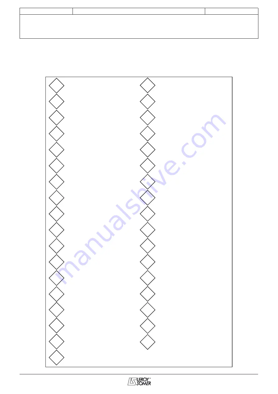
5.11 - Menu 10: Status and trips

5.11.1 - Menu 10 dia

g

rams

Drive healthy

Drive active

Zero speed

Running at minimum speed

Below set speed

At speed

Above set speed

Nominal load reached

Drive output at current limit

Drive regenerating

Braking IGBT active

Direction commanded

Direction running

Mains loss

DC bus undervoltage

Motor overload alarm

Drive overtemperature alarm

Drive general warning

Last trip
(most recent trip)

Trip - 2

Trip - 3

Trip - 4

Trip - 5

Trip - 6

Trip - 7

Trip - 8

Trip - 9

Trip - 10
(oldest trip)

Status word 

10.01

 to 

10.15

Vmin alarm

Vmax alarm

Maximum speed

DC bus preload contactor closed

Drive status

Current trip

• Operating states

10.01

10.02

10.20

10.03

10.21

10.04

10.22

10.05

10.23

10.06

10.24

10.07

10.25

10.08

10.26

10.09

10.27

10.10

10.28

10.11

10.29

10.13

10.40

10.14

10.51

10.15

10.16

10.17

10.18

10.19

10.52

10.53

10.76

10.98

10.99

Summary of Contents for POWERDRIVE MD

Page 1: ...t Digital input or output 2 Output Input Digital input polarity Positive Negative 0 1 08 01 08 31 08 11 08 02 08 32 08 12 8 29 MENU 14 PID controller MENU 0 Refer to section MENU 8 Configuration of di...

Page 2: ...motor restarting after an unscheduled stop The variable speed drive is designed to be able to supply a motor and the driven machine above its rated speed If the motor or the machine are not mechanical...

Page 3: ...ic conditions specified in the technical manual must be observed 4 Installation The installation and cooling of equipment must comply with the specifications in the manual supplied with the product Th...

Page 4: ...4 COMMISSIONING MANUAL POWERDRIVE MD Variable speed drive LEROY SOMER 3871 en 2011 05 h Notes...

Page 5: ...uction 36 5 1 1 Menu organisation 36 5 1 2 Explanations of symbols used 37 5 2 Menu 1 Speed references and limitations 38 5 2 1 Menu 1 diagrams 38 5 2 2 Explanation of parameters in menu 1 40 5 3 Menu...

Page 6: ...0 5 17 1 Menu 16 diagrams 120 5 17 2 Explanation of parameters in menu 16 121 5 18 Menu 17 Diagnostics 124 5 19 Menu 18 Regenerative mode MDR 129 5 19 1 Menu 18 diagram 129 5 19 2 Explanation of param...

Page 7: ...ical value or parameter number to be entered Temperature operating range 0 C to 50 C A lithium battery allows back up of parameters for 10 years without any power up After 10 minutes without activity...

Page 8: ...es of Read mode Pressing displays the number pad used for selecting the parameter number Press ENT to confirm CAUTION Only read only parameters can be configured here Parameters 5 04 and 4 01 are the...

Page 9: ...s to menu 0 and groups together the most common parameters See Section 2 4 5 1 parameter list in the commissioning manual 2 2 3 2 User set up USER SET UP allows access to 10 parameters 00 56 to 00 65...

Page 10: ...ted by a code to the parameters for programming the various functions available on the HMI in three separate sub menus USER SET UP ASSIGNMENTS used to configure the 10 user parameters 00 56 to 00 65 A...

Page 11: ...ble drive parameters from menu 1 to menu 21 These various parameters are accessible for reading and writing Press the button corresponding to the number of the user parameter to be modified then type...

Page 12: ...time SET UP TIME enables the user to set the drive s date and time Press one of the touch buttons corresponding to the setting to be modified Using the number pad type in the new value then press ENT...

Page 13: ...eference are displayed No Run Fwd Run Backwd Stop command via the HMI Two buttons Forward and Stop are displayed Three buttons Forward Stop and Backward are displayed Setup possible Effects on the KEY...

Page 14: ...en follow the parameter setting procedure described in Section 2 2 3 4 Screen in factory settings Configured screen see Section 2 2 3 4 This ACTIVE TRIP screen is displayed when the drive trips Press...

Page 15: ...hing Trip button takes priority The Stop button then becomes inaccessible see TRIP HISTORY screen Section 2 2 5 2 3 Communication loss alarm If communication between the drive and the HMI is broken th...

Page 16: ...ion 2 2 3 1 Check that 00 13 OPEN LOOP If not return to factory settings 00 45 50 Hz HIGH or LOW for a 400 V 50 Hz supply or 60 Hz HIGH or LOW for a 460 V 60 Hz supply 00 45 automatically returns to D...

Page 17: ...2 Stationary Enable the drive connect terminals SDI1 and SDI2 Give a run forward or reverse command with factory settings close DI4 or DI5 Check that 00 42 Off autotuning complete Remove the run comma...

Page 18: ...f lines Encoder 5V 1024 Hall sensor 15V In read mode on the parameter setting interface the operating status displays DISABLED or Encoder break Switch on the drive Open the contact SDI1 SDI2 In parame...

Page 19: ...5 17 05 24 Enter the other motor and control parameters Enter the encoder phase angle manually in 00 17 located on the motor nameplate Possible to uncouple the motor YES NO Autotuning with rotation Co...

Page 20: ...erminal block ADI3 0V terminals and set 00 28 CTP 1 Enter the main parameters 00 06 MOTOR RATED CURRENT A 00 07 MOTOR RATED SPEED rpm 00 08 MOTOR RATED VOLTAGE V 00 10 MOTOR RATED FREQUENCY Hz 05 24 E...

Page 21: ...07 0 to Ico A depends on the rating refer to section 5 6 3 00 07 MOTOR RATED SPEED 05 08 1 to 32000 rpm depends on the rating refer to section 5 6 3 00 08 MOTOR RATED VOLTAGE 05 09 0 to 999 V 400 V 0...

Page 22: ...25 ANALOG INPUT 1 MODE 07 06 0 20 mA 20 0 mA 4 20 trip 20 4 trip 4 20 no trip 20 4 no trip 0 10 V 10V 10V 00 26 ANALOG DIGITAL INPUT 2 MODE 07 11 0 20 mA 20 0 mA 4 20 trip 20 4 trip 4 20 no trip 20 4...

Page 23: ...12 2 00 46 PRESET REFERENCE 1 01 21 00 02 rpm 0 rpm 00 47 PRESET REFERENCE 2 01 22 00 02 rpm 0 rpm 00 48 PRESET REFERENCE 3 01 23 00 02 rpm 0 rpm 00 49 PRESET REFERENCE 4 01 24 00 02 rpm 0 rpm 00 50 C...

Page 24: ...ocks section in the drive installation manual Analog 1 1 In factory setting mode the speed reference is selected via digital input DIO2 as follows Analog 2 2 In factory setting mode the speed referenc...

Page 25: ...contact LEROY SOMER CAUTION A high switching frequency reduces the magnetic noise however it increases the drive temperature rise Refer to the installation manual to determine the derating of the dri...

Page 26: ...drive output active RS POWER UP 4 The stator resistance and voltage offset are measured the first time the drive is enabled drive output active following each power up V F SQUARE 5 Square law characte...

Page 27: ...er of factors internal to the drive oscillations may occur in the following cases Frequency control with current limiting around the rated frequency and on load impacts Torque control on machines with...

Page 28: ...20 4 trip 3 4 20 no trip 4 20 4 no trip 5 0 10 V 6 10 V 7 Factory setting 10 V 7 Used to define the type of signal on the AI1 input Analog digital input 2 mode Adjustment range 0 20 mA 0 20 0 mA 1 4...

Page 29: ...p sequencing bit 00 36 10 33 Trip reset Note Any unprotected bit type parameter can be assigned to the input If an unsuitable parameter is addressed no assignment is taken into account Logic type for...

Page 30: ...de chosen in parameter 00 40 When zero frequency is reached the drive injects DC current for 1 second The drive is then ready DC to 0 3 Stop by DC injection braking and elimination at zero speed The d...

Page 31: ...isable input must be closed At the end of the test if a Diagnostics fault appears read the result in 17 11 and then get in touch with your usual LEROY SOMER contact Caution during this test current is...

Page 32: ...etting 0 Used to define preset reference Pr3 Preset reference 4 Adjustment range 00 02 rpm Factory setting 0 Used to define preset reference Pr4 Catch a spinning motor Adjustment range DISABLED 0 2 DI...

Page 33: ...500 rpm Factory setting 30 rpm Defines the window within which the At speed alarm is activated This alarm is activated when the post ramp reference equals the reference 00 52 2 Delay before mains loss...

Page 34: ...e XPressKey Connect the configuration interface Using the configuration interface check that the drive is disabled terminal SDI open After configuring 00 44 Drive o key disconnect the configuration in...

Page 35: ...ated using the pushbutton located on the copy key A first press on the button corresponds to parameter 00 44 changing to Key o drive the XPressKey LED flashes slowly A second press on the button confi...

Page 36: ...references and limitations MENU 7 PX1 PX2 PX3 Configuration of analog I O MENU 2 Ramps MENU 3 Alarms speed thresholds encoder option Motor control mode switching frequency characteristics MENU 9 Logi...

Page 37: ...with Read Only access and are write protected They are used to provide information concerning operation of the drive and can be designated as an assignment source for connection to Digital outputs fo...

Page 38: ...selected 0 0 0 0 1 1 1 1 1 2 3 4 5 6 7 8 0 0 1 1 0 0 1 1 0 1 0 1 0 1 0 1 Percentage trim Offset validation Reference offset A AI1 AI1 ADI2 DIO1 DIO2 DIO3 DI4 DI5 100 Menu 7 Menu 8 0 0 1 1 1 2 3 4 0 1...

Page 39: ...reference 1 2 Reference in skip zone 1 1 0 0 0 1 X 1 1 0 1 OR Skips Skip Reference band 0 MENU 8 MENU 6 Jog indicator Bipolar reference enable Jog reference Reverse select indicator Reference enable i...

Page 40: ...he new value of 01 06 Not used Offset validation Adjustment range Ref x 01 38 0 or Ref 01 04 1 Factory setting Ref x 01 38 0 Ref x 01 38 0 A value proportional to this reference is added to the main r...

Page 41: ...ip reference bands 1 and 2 Adjustment range 0 to 300 rpm Factory setting 15 rpm Define the skip band around the avoided speed The total skip will therefore equal the threshold set skip reference band...

Page 42: ...Time between each reference Adjustment range Same 0 or Different 1 Factory setting Same 0 Same 0 The time for which the drive remains on each preset reference is the same for all references Different...

Page 43: ...43 COMMISSIONING MANUAL POWERDRIVE MD Variable speed drive MENUS AND DIAGRAMS IN ADVANCED SET UP MODE LEROY SOMER 3871 en 2011 05 h Notes...

Page 44: ...selector Selected preset reference indicator Binary sum output Menu 1 Menu 1 Jog indicator S ramp acceleration limit S ramp enable Acceleration rate 1 Acceleration rate 2 Acceleration rate 3 Accelera...

Page 45: ...rate 4 Deceleration rate 5 Deceleration rate 6 Deceleration rate 7 Deceleration rate 8 Ramp hold Ramp hold condition Ramp bypass 1 0 1 0 0 1 2 3 4 5 6 7 8 A B C V min 0 0 Run forward 0 or 1 2 or 3 Ru...

Page 46: ...bus overvoltage CAUTION In modes 2 and 3 the motor must be capable of tolerating additional losses relating to the increase in voltage at its terminals Not used S ramp enable Adjustment range Off 0 or...

Page 47: ...te 3 Deceler 4 4 Deceleration rate 4 Deceler 5 5 Deceleration rate 5 Deceler 6 6 Deceleration rate 6 Deceler 7 7 Deceleration rate 7 Deceler 8 8 Deceleration rate 8 To preset 9 The ramp is automatical...

Page 48: ...53 with the deceleration ramp defined by 02 55 then decelerates to 0 with the ramp defined by 02 21 to 02 28 2 Acc Decel 3 Double acceleration and deceleration ramps The drive accelerates or decelera...

Page 49: ...speed threshold Zero speed threshold Minimum speed Minimum reference clamp Vmin alarm Vmin alarm threshold Minimum reference clamp Vmax alarm Vmax alarm threshold Maximum speed Maximum reference clam...

Page 50: ...threshold Zero speed threshold Minimum speed Vmin alarm Vmin alarm threshold Minimum reference clamp 2 Maximum speed Maximum reference clamp Vmax alarm Vmax alarm threshold Maximum reference clamp 2 K...

Page 51: ...speed drive MENUS AND DIAGRAMS IN ADVANCED SET UP MODE LEROY SOMER 3871 en 2011 05 h Encoder feedback option continued Speed gain select Speed gain setup Total inertia Bandwidth Damping factor Remanen...

Page 52: ...in speed both at no load and on load Speed loop integral gain Ki1 Adjustment range 0 to 32000 Factory setting 100 Sets the stability of the motor speed on load impact Increase the integral gain to li...

Page 53: ...UVW only 2 Increm UVW 3 HALL EFFECT 4 SENSORLESS 1 to 5 5 to 9 RESOLVER 10 Factory setting INCREMENTAL 0 INCREMENTAL 0 Quadrature incremental encoder Increm FD 1 Incremental encoder with Frequency Di...

Page 54: ...ment range 0 to 500 rpm Factory setting 90 rpm Triggers an alarm 10 51 when the motor speed is such that 05 04 V min 01 07 or 21 02 03 51 in open loop mode 03 02 V min 01 07 or 21 02 03 51 in closed l...

Page 55: ...55 COMMISSIONING MANUAL POWERDRIVE MD Variable speed drive MENUS AND DIAGRAMS IN ADVANCED SET UP MODE LEROY SOMER 3871 en 2011 05 h Notes...

Page 56: ...current A Magnetising current A Current magnitude A Percentage load User max current scaling User max current scaling Drive output is at current limit Motor torque per amp conversion Drive output is a...

Page 57: ...e delay Torque mode selector Internal setting for reactive current Torque offset selection Active current A Percentage load User max current scaling Magnetising current A Current magnitude A Drive out...

Page 58: ...mode the only current limit is 04 07 Motor actif current is in relation with the power factor and motor rated current Torque reference Adjustment range 04 24 motor active In Factory setting 0 0 In Mai...

Page 59: ...ransient limit of the drive current This value depends on 04 05 04 06 04 51 and internal limits Overload accumulator Adjustment range 0 to 100 This parameter indicates the estimated thermal state of t...

Page 60: ...tation direction Disable automatic adjustment of the switching frequency Absorbed power V x I x V 3 Rated frequency Rated current Rated speed Rated voltage Rated power Factor Number of motor poles Sta...

Page 61: ...of the motor shown on the nameplate Note This value must take into account the slip of the asynchronous motor with respect to the synchronous speed Under no circumstances must this slip be negative M...

Page 62: ...frequency characteristic which varies with the load It is for use in quadratic torque applications pumps fans compressors It can be used in constant torque applications with low dynamics to reduce mot...

Page 63: ...ht increase in motor noise Quasi square output Adjustment range Disabled 0 or Enabled 1 Factory setting Enabled 1 Disabled 0 Function disabled Enabled 1 The maximum drive output voltage is higher resu...

Page 64: ...ion 11 31 SERVO define the parking time before the motor start to run If total inertia 03 18 is higher than 10 kg m2 the packing time is multiplied by 03 18 value In closed loop application 11 31 CL L...

Page 65: ...lication 05 63 Heavy duty Normal duty Europe USA Europe USA Rating 05 07 00 06 05 08 00 07 05 07 00 06 05 08 00 07 05 07 00 06 05 08 00 07 05 07 00 06 05 08 00 07 270TH 224 1486 209 1785 224 1487 209...

Page 66: ...erminals 24 V Run forward Run reverse Stop DI4 DI5 DIO3 MENU 8 24 V Run Stop Forward Reverse sequencing bit DI4 DI5 MENU 8 24 V Run FWD Stop Run REV Stop DI4 DI5 MENU 8 SEQUENCER 1 0 1 2 3 0 Stop mode...

Page 67: ...IN ADVANCED SET UP MODE LEROY SOMER 3871 en 2011 05 h Clock Run Stop command Clock Run time Hours Minutes Years Days Energy meter kW h MW h Powered up time Years days h min Reset Energy meter Output...

Page 68: ...efined by parameter 06 07 The drive is ready DC to 0 3 Stop by braking by low frequency current injection then DC injection at zero speed The drive decelerates the motor by imposing a low frequency cu...

Page 69: ...Stop 1 Command for Run and Stop via jog contacts In this mode use DIO3 to give the Stop command To do this configure 08 23 06 39 DIO3 assigned as Stop input Terminal DI4 preset to Run FWD Terminal DI5...

Page 70: ...turns this operation may cause the machine to rotate in both directions before the motor accelerates Before enabling this function check that there is no danger to equipment and personnel In some case...

Page 71: ...read write type parameters they are volatile and are not stored when the drive is powered down Each time the drive is powered up they will be reset to Disabled 0 06 30 Run FWD sequencing bit 06 31 Jog...

Page 72: ...Keypad 3 or Fieldbus 1 This will force 08 10 to Drive enable and only conformity to EN954 1 category 1 will be provided On return of the value 06 43 to Terminals parameter 08 10 remains at Drive enabl...

Page 73: ...73 COMMISSIONING MANUAL POWERDRIVE MD Variable speed drive MENUS AND DIAGRAMS IN ADVANCED SET UP MODE LEROY SOMER 3871 en 2011 05 h Notes...

Page 74: ...AI1 Input ADI3 PTC state MD Encoder PTC state 0 2 1 Scaling Scaling Scaling 100 4 20 no trip 20 4 no trip 20 4 trip 4 20 trip 20 0 mA 0 10V 10 V 1 0 to 6 7 0 6 1 2 0 20 mA 0 3 4 5 7 Destination X 1 AI...

Page 75: ...rce Signal type Signal type Absolute value Absolute value 0 1 2 0 1 2 Output AO1 Output AO2 AO1 10V 0 20mA 4 20mA AO2 10V 0 20mA 4 20mA Module U temperature Rectifier temperature Module V temperature...

Page 76: ...l not inverted Enabled 1 Input signal inverted Analog input 1 destination Adjustment range 00 00 to 21 51 Factory setting 01 36 Analog input 1 assigned to analog reference 1 This address should contai...

Page 77: ...and AO2 Adjustment range 00 00 to 21 51 Factory setting 04 01 AO1 05 04 AO2 This address should contain the number of the parameter which you wish to assign to the analog outputs and Analog output sca...

Page 78: ...er min value Example ADI2 is assigned to a parameter with an adjustment range of 0 30000 If 07 59 0 01 0 100 on ADI2 corresponds to 300 30000 07 59 is not used when input ADI2 is used as a 10 V input...

Page 79: ...79 COMMISSIONING MANUAL POWERDRIVE MD Variable speed drive MENUS AND DIAGRAMS IN ADVANCED SET UP MODE LEROY SOMER 3871 en 2011 05 h Notes...

Page 80: ...Digital input or output 1 Output Input Source or Reference selection DIO2 1 1 1 0 0 0 Input or output selection DIO2 state Invert Destination Digital input or output 2 Output Input Source or Reference...

Page 81: ...atus SDI state Secure disable select Digital I O read word Buffer variable 1 Buffer variable 2 Buffer variable 3 Buffer variable 4 Source SDI2 SDI1 SDO1 SDO2 RL2O COM RL2 Secure disable input redundan...

Page 82: ...he drive must be connected in accordance with the recommended diagram in the installation manual supplied with the drive Note Modifications to 08 10 must be made with the SDI1 SDI2 contact open The se...

Page 83: ...ct the destination of input DI5 Any non protected bit type parameter can be assigned to the input If an unsuitable parameter is addressed no assignment is taken into account Not used Relay 1 output so...

Page 84: ...ET UP MODE LEROY SOMER 3871 en 2011 05 h to Buffer variables 1 to 4 Adjustment range Disabled 0 or Enabled 1 Factory setting Disabled 0 Binary parameters that can be used as buffer variables CAUTION A...

Page 85: ...85 COMMISSIONING MANUAL POWERDRIVE MD Variable speed drive MENUS AND DIAGRAMS IN ADVANCED SET UP MODE LEROY SOMER 3871 en 2011 05 h Notes...

Page 86: ...09 64 09 66 09 65 09 67 09 68 09 61 09 60 Function 4 09 74 09 76 09 75 09 77 09 78 09 71 09 70 Source 1 Source 2 Source 3 Source 1 invert Source 2 invert Source 3 invert Output invert Output Destinat...

Page 87: ...entiometer reference Destination Motorised pot mode Motorised pot reset 100 0 100 100 0 t Polarity Rate 09 26 09 27 09 28 09 03 09 21 09 24 09 25 09 22 09 23 Output Destination Binary sum output offse...

Page 88: ...d 0 Output not inverted Enabled 1 Output inverted Not used Logic 1 output destination Adjustment range 00 00 to 21 51 Factory setting 00 00 This parameter defines the internal parameter which will be...

Page 89: ...wn pot reference automatically takes the maximum value of the parameter to which it is assigned This parameter can therefore be used to adapt the maximum value of the up down pot reference to the maxi...

Page 90: ...source 1 for logic function 3 Only bit type parameters can be used on these inputs If an unsuitable parameter is addressed the input will be frozen at 0 Logic 3 source 1 invert Adjustment range Disab...

Page 91: ...e of the output of logic function 5 Logic function 5 source 3 Adjustment range 00 00 to 21 51 Factory setting 10 19 This parameter is used to select source 3 for logic function 5 Only bit type paramet...

Page 92: ...inverted Enabled 1 Source 3 inverted Logic function 6 source 1 Adjustment range 00 00 to 21 51 Factory setting 00 00 This parameter is used to select source 1 for logic function 6 Only bit type param...

Page 93: ...93 COMMISSIONING MANUAL POWERDRIVE MD Variable speed drive MENUS AND DIAGRAMS IN ADVANCED SET UP MODE LEROY SOMER 3871 en 2011 05 h Notes...

Page 94: ...tion commanded Direction running Mains loss DC bus undervoltage Motor overload alarm Drive overtemperature alarm Drive general warning Last trip most recent trip Trip 2 Trip 3 Trip 4 Trip 5 Trip 6 Tri...

Page 95: ...healthy auto reset Brak IGBT management stop minor trip Serial link user trip User alarm 1 User alarm 2 User alarm 3 User alarm 4 Motor phase missing trip validation I imbalanced trip validation User...

Page 96: ...0 or Enabled 1 This parameter is at Enabled 1 when the absolute value of the motor speed is between 01 03 03 06 2 and 01 03 03 06 2 Above set speed Adjustment range Disabled 0 or Enabled 1 This param...

Page 97: ...4 TUNE U Encod Some encoder signals are present but commutation channel U is missing 15 TUNE V Encod Some encoder signals are present but commutation channel V is missing 10 16 10 17 10 18 10 19 10 20...

Page 98: ...s due to IGBT overcurrent Brak IGBT either at the output bridge Drive output current or the braking transistor the drive cannot be reset for 10 seconds IGBT recovery time Number of auto reset attempts...

Page 99: ...ustment range 0 to 100 0 This parameter gives an indication of the braking resistor temperature modelled according to parameters 10 30 and 10 31 A zero value means that the resistor is close to the am...

Page 100: ...1 The drive trips decelerates in freewheel mode and generates a User trip 4 code Not used Trip active at standstill Adjustment range OFF 0 or On 1 Factory setting On 1 This parameter is used to make d...

Page 101: ...motor 10 TLSP STOP G Stop by low frequency current injection counter clockwise generator 15 DC Inject M DC injection clockwise motor 16 DC Inject G DC injection clockwise generator 17 DC Inject M DC i...

Page 102: ...ress Baud rate Min comms transmit delay Parity number of stop bits Parameter 47 assignment Parameter 48 assignment Parameter 49 assignment Parameter 50 assignment Parameter 51 assignment Parameter 52...

Page 103: ...for communication between the drive and the HMI to be established Min comms transmit delay Adjustment range 0 to 100 ms Factory setting 10 ms As the serial link is 2 wire type Rx is connected to Tx a...

Page 104: ...to the drive the XPressKey LED is then on continuously The LED going out indicates the end of the transfer Disconnect the XPressKey and reconnect the interface cable Note If the transfer cannot be per...

Page 105: ...t per 1000 rpm Ke 05 51 21 51 Q axis inductance synchronous motor 11 45 to Not used Drive identification code Adjustment range 0 to 32000 This product code gives information on the drive rating size h...

Page 106: ...enus Communication type between drives Adjustment range NONE 0 Invert REGEN 1 Rectif REGEN 2 MASTER TWIN 3 SLAVE TWIN 4 MASTER Synch 5 SLAVE Synchr 6 Factory setting NONE 0 0 NONE 1 Invert REGEN 2 Rec...

Page 107: ...rator 4 12 73 12 74 12 75 12 71 12 76 12 77 Source Scaling Source Scaling Selection Applied Destination Output Variable 1 Variable 1 Variable 2 Variable 2 function factor output Block 1 12 08 12 13 12...

Page 108: ...threshold Brake release frequency threshold Brake apply frequency threshold Sequencing 0 0 1 1 3 2 Brake control enable Post brake release delay Forced brake release Drive active Pre brake release del...

Page 109: ...elay Brake control enable Hold zero speed Ramp hold AND OUT IN IN OR OUT IN IN LATCH OUT ON OFF IN Disabled On contactor On relay User select Motor speed Absolute value Speed threshold delay Run Stop...

Page 110: ...d If an unsuitable parameter is programmed the output is not sent anywhere Function 1 variable 1 source Adjustment range 00 00 to 21 51 Factory setting 00 00 This parameter defines the source paramete...

Page 111: ...ld The absolute value of the variable is used Only non bit parameters can be programmed as the source If an unsuitable parameter is programmed the input value is taken to equal 0 Comparator 2 threshol...

Page 112: ...order filter the associated parameter is used as a time constant if it is used to generate a ramp this parameter is used to adjust the value of the ramp in seconds The ramp time corresponds to the ti...

Page 113: ...ge 0 to 25 00 s Factory setting 1 00 s This time delay is triggered when brake control is enabled It is used to allow time for the brake to release before unlocking the ramp 02 03 Off 0 Brake apply de...

Page 114: ...ange 00 00 to 21 51 Factory setting 00 00 This parameter defines the variable that is to be compared to the configured threshold The absolute value of the variable is used Only non bit parameters can...

Page 115: ...115 COMMISSIONING MANUAL POWERDRIVE MD Variable speed drive MENUS AND DIAGRAMS IN ADVANCED SET UP MODE LEROY SOMER 3871 en 2011 05 h 5 14 MENU 13 Reserved...

Page 116: ...eference invert PID reference slew rate limit PID output value PID feedback invert PID output scaling PID output destination X 1 1 0 X 1 PID hold integrator PID feedback PID main reference PID option...

Page 117: ...The PID controller is disabled Enabled 1 The PID controller is enabled PID option enable source Adjustment range 00 00 to 21 51 Factory setting 10 01 This parameter is used to enable the PID controlle...

Page 118: ...nabled 1 14 13 and 14 14 take the same value and 14 13 is the parameter that takes effect PID main reference Adjustment range 100 0 This parameter indicates the value of the main reference PID referen...

Page 119: ...IVE MD Variable speed drive MENUS AND DIAGRAMS IN ADVANCED SET UP MODE LEROY SOMER 3871 en 2011 05 h 5 16 Menu 15 MODBUS RTU and Fieldbus connection options and additional I O Please consult the manua...

Page 120: ...16 04 16 01 16 09 Timer 2 16 12 16 13 16 15 16 14 16 11 16 19 Timer 3 16 22 16 23 16 25 16 24 16 21 16 29 Timer 4 16 32 16 33 16 35 16 34 16 31 16 39 ON source OFF source Output state Output destinat...

Page 121: ...parameter indicates the state of the output of timer 2 Timer 2 source Adjustment range 00 00 to 21 51 Factory setting 00 00 This parameter is used to select the input source for timer relay 2 Only bit...

Page 122: ...lay is used for on delay timing The output changing to Enabled 1 is delayed in relation to the input changing to 1 OFF timer 1 The relay is used for off delay timing The output changing to Disabled 0...

Page 123: ...o change to Enabled 1 Only bit type parameters can be assigned to this input If an unsuitable parameter is addressed the input will be frozen at 0 Latch 3 OFF source Adjustment range 00 00 to 21 51 Fa...

Page 124: ...e drive must control the preloading of capacitors on the DC bus therefore 10 75 must be set to NO 0 NO 0 The power self test is not enabled YES 1 Enabling of the power module test which will be perfor...

Page 125: ...cluding after the power supply to the electronics is disconnected to Not used Average supply voltage Adjustment range 0 to 999 V Average supply voltage at the time of the last drive trip filtered by 1...

Page 126: ...y setting is usually suitable Value of the speed at the time of the trip instant 0 Adjustment range 32000 rpm This value is stored including after the power supply to the electronics is disconnected V...

Page 127: ...This is the drive status before the trip This value is stored including after the power supply to the electronics is disconnected Time between status Adjustment range 0 to 32 767 s Indicates the time...

Page 128: ...n fault 2 Adjustment range 0 000 to 9 364 y ddd Counter 2 duration fault 2 Adjustment range 00 00 to 23 59 hh mm These counters indicate the operating time since the drive was first commissioned until...

Page 129: ...rd 2 Active power DC bus voltage in Regen mode Mains voltage Mains frequency Line inductance value Active current measurement Total current measurement Reactive current measurement Reactive current Ac...

Page 130: ...ersion DC voltage set point Adjustment range 0 to 1300 V Factory setting T 660 V TH 1070 V The sinusoidal rectifier sets the DC bus to the level specified by this parameter The bus voltage must always...

Page 131: ...ffective current limit value of the Regen drive This value depends on 18 19 and limits internal to the drive Symmetric current limit Adjustment range 0 0 to 300 0 active In Factory setting 150 0 Used...

Page 132: ...ster controlling the DC bus voltage and the slave controlling the current reference 18 29 CAUTION This tandem operation requires the rectifiers to be connected in a specific manner Please consult LERO...

Page 133: ...000 rpm Factory setting 20 0 s 1000 rpm Sets the time for acceleration from 0 to 1000 rpm 21 04 This parameter is equivalent to 02 11 in motor 1 Motor 2 deceleration rate Adjustment range 0 to 3200 0...

Page 134: ...an important role in low speed operation i e when the drive output voltage is low During autotuning 05 12 Stationary 1 or Rotating 2 the value of the voltage offset is automatically stored This param...

Page 135: ...MD 24Vs should not be connected 6 2 Parameter setting using the PC With the POWERSOFT configuring software setting up the POWERDRIVE MD from a PC is very user friendly Quick configuration the drive pa...

Page 136: ...This silence period indicates the end of the message and the slave can start to process the transmitted data All data is encoded in hexadecimal format All master requests will lead to a response from...

Page 137: ...e limit is exceeded the slave does not respond Note 99 parameters maximum can be read Frame sent by the Master Frame returned by the slave Where n 3 number of bytes to be read Drive parameter Register...

Page 138: ...es Description 0 Slave address 1 to 247 1 Function code 0x10 2 Start word address MS byte 3 Start word address LS byte 4 Number of words to be written MS byte 5 Number of words to be written LS byte 6...

Page 139: ...lave timeout If a write request function code 16 or 23 exceeds the maximum size accepted by the slave then the slave will reject the message No exception will be transmitted and the master will not re...

Page 140: ...6 bits from all the bytes in the question and response frames Algorithm START CRC 0xFFFF Number of bytes processed 0 Next byte first byte REPEAT Byte to be processed next byte CRC CRC XOR byte to be p...

Page 141: ...long Reduce the speed loop gains 00 18 03 10 00 19 03 11 and 03 12 If it has not already been done perform autotuning 00 42 2 Reduce the current loop gains 04 13 and 04 14 This trip cannot be reset fo...

Page 142: ...ilters 24 Motor PTC Triggering of motor thermal sensor on ADI3 or MD Encoder Check the motor load Reduce the overload level Check the motor ventilation and the ambient temperature Check the wiring of...

Page 143: ...red via serial link See 10 38 See 10 37 51 PXIO EEPROM Problem on PX I O EEPROM Power down and then power up again Return to factory settings see 00 45 52 PXIO power Overload of the PX I O power suppl...

Page 144: ...0 DIAGNOSTIC Problem detected during the control and interface board test the power module test or the self test Check that the SDI input is closed Look at parameters 17 01 17 02 and 17 03 Read the te...

Page 145: ......

Page 146: ...MOTEURS LEROY SOMER 16015 ANGOUL ME CEDEX FRANCE 338 567 258 RCS ANGOUL ME Limited company with capital of 62 779 000 www leroy somer com...

Reviews: