


2
8
COMMISSIONING MANUAL
POWERDRIVE MD
Variable speed drive
PARAMETER SETTING INTERFACE
LEROY-SOMER
3871 en - 2011.05 / h
: Run/Stop source
Adjustment range : TERMINALS (0), FIELDBUS (1),
NOT ACTIV (2), LCD Keypad (3)
Factory setting
: TERMINALS (0)
Terminals (0): Commands come from the terminals.
Fieldbus (1):
Commands come from the control word
(see
06.42
in menu 6, section 5.7).
NOT ACTIV (2):
Not used.
LCD Keypad (3):
Commands come from the configuration
interface.
Note:
Modifications to
00.23
must be made with the drive
disabled.
CAUTION:
• The confi
g
uration interface Stop key, if enabled, is
reco
g
nised irrespective of the source of the commands.
If a stop is caused by the confi
g
uration interface Stop key
while the commands are comin
g
from the terminals or
the fieldbus (
00.23
= TERMINALS (0) or FIELDBUS (1))
and a run command is present, the run command must
g
o back to 0 and then 1 in order to be taken into account.
• When the secure disable function is enabled
00.24
=
SECUR. DISAB. (1), the value of
00.23
is automatically
set to "TERMINALS" (0). Even so, the user can chan
g
e
this value to "LCD KEYPAD" (3) or "FIELDBUS" (1).
This will force
00.24
to "DRIVE ENABLE", and only
conformity to EN954-1 cate
g
ory 1 will be provided.
: Secure disable select
Adjustment range : DRIVE ENABLE (0) or
SECUR. DISAB. (1)
Factory setting
: SECUR. DISAB. (1)
DRIVE ENABLE (0):
The SDI input is used as a simple
enabling input.
SECUR. DISAB. (1): The SDI input is used as a secure
disable input. In order to conform to safety standard
EN954-1 cate
g
ory 3, the drive must be connected in
accordance with the recommended dia
g
ram in the
installation manual supplied with the drive.
Note:
Modifications to
00.24
must be made with the
SDI1/SDI2 contact open.
• The secure disable input function is disabled
automatically,
00.24
chan
g
es to DRIVE ENABLE
(0), when the drive is controlled via the confi
g
uration
interface or fieldbus, for example, when
00.23
= Fieldbus
(1) or LCD KEYPAD (3). Only conformity to EN954-1
cate
g
ory 1 will be provided.
: Analo
g
input 1 mode
Adjustment range : 0-20 mA (0), 20-0 mA (1),
4-20 trip (2),
20-4 trip (3),
4-20 no trip (4),
20-4 no trip (5), 0-10 V (6),
+/-10 V (7)
Factory setting
: +/-10 V (7)
Used to define the type of signal on the AI1 input.
: Analo
g
/di
g
ital input 2 mode
Adjustment range : 0-20 mA (0), 20-0 mA (1),
4-20 trip (2),
20-4 trip (3),
4-20 no trip (4),
20-4 no trip (5), 0-10 V (6),
+/-10 V (7), Digital in (8)
Factory setting
: 4-20 no trip (4)
Used to define the type of signal on the ADI2 input.
: Not used
: Analo
g
/di
g
ital input 3 mode
Adjustment range : 0-10 V (0), CTP (1), Digital in (2)
Factory setting
: 0-10 V (0)
To enable management of the motor PTC sensor, connect
the sensor between ADI3 and 0 V, and then configure
00.28
as CTP (1).
Note:
The other functions of
00.28
are not used from menu 0.
: AO1 analo
g
output mode
Adjustment range : +/-10V (0), 0-20mA (1), 4-20mA (2)
Factory setting
: 4-20mA (2)
+/-10V (0):
±10 V voltage output.
0-20mA (1):
0 to 20 mA current output.
4-20mA (2): 4 to 20 mA current output.
Selection of the type of signal on the analog output
(current image).
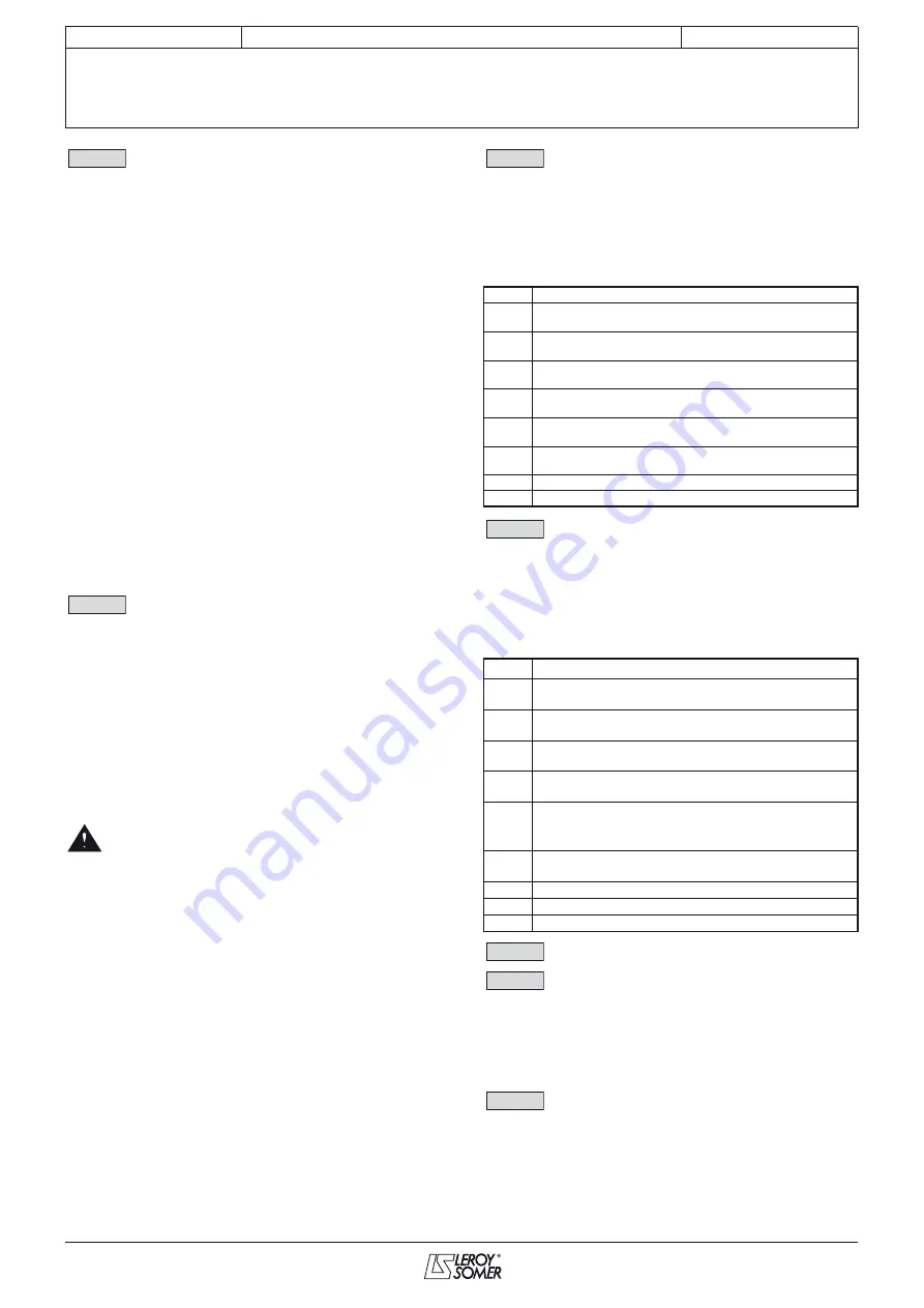
00.23
00.24
00.25
Description
0
0-20 mA current signal, 0 mA corresponds to the
minimum reference
1
20-0 mA current signal, 20 mA corresponds to the
minimum reference
2
4-20 mA current signal with detection of signal loss.
4 mA corresponds to the minimum reference
3
20-4 mA current signal with detection of signal loss.
20 mA corresponds to the minimum reference
4
4-20 mA current signal without detection of signal
loss. 4 mA corresponds to the minimum reference
5
20-4 mA current signal without detection of signal
loss. 20 mA corresponds to the minimum reference
6
0-10 V voltage signal
7
±10 V volta
g
e si
g
nal
00.26
Description
0
0-20 mA current signal, 0 mA corresponds to the
minimum reference
1
20-0 mA current signal, 20 mA corresponds to the
minimum reference
2
4-20 mA current signal with detection of signal loss.
4 mA corresponds to the minimum reference
3
20-4 mA current signal with detection of signal loss.
20 mA corresponds to the minimum reference
4
4-20 mA current si
g
nal without detection of
si
g
nal loss. 4 mA corresponds to the minimum
reference
5
20-4 mA current signal without detection of signal
loss. 20 mA corresponds to the minimum reference
6
0-10 V voltage signal
7
±10 V voltage signal
8
The input is configured as a digital input
00.25
00.26
00.27
00.28
00.29