


26
COMMISSIONING MANUAL
POWERDRIVE MD
Variable speed drive
PARAMETER SETTING INTERFACE
LEROY-SOMER
3871 en - 2011.05 / h
: Open loop mode select (
)
Encoder type (
)
:
Adjustment range : RS: EACH RUN (0),
RS: NO Mes. (1),
LINEAR V/F (2),
RS: 1st RUN (3),
RS: POWER UP (4),
V/F SQUARE (5)
Factory setting
: RS: NO Mes. (1)
Determines the open loop control mode.
Modes 0, 1, 3 or 4 are used in flux vector control. The
difference between these modes is the method used to identify
the motor parameters, in particular the stator resistance. As
these parameters vary with temperature and are essential for
obtaining optimum performance, the machine cycle must be
taken into account for selecting the most appropriate mode.
Modes 2 and 5 correspond to a V/F ratio control mode. This
ratio is linear in mode 2 and square in mode 5.
RS: EACH RUN (0):
The stator resistance and voltage offset
are measured each time the drive receives a run command.
These measurements are only valid if the machine is stopped
and totally defluxed. The measurement is not taken when the
run command is given less than 2 seconds after the previous
stop. This is the most effective flux vector control mode.
However, the operating cycle must be compatible with the
2 seconds required between a stop command and a new run
command.
RS: NO Mes. (1): The stator resistance and volta
g
e offset
are not measured. This mode is of course the least
effective. It should only be used when mode 0 is
incompatible with the operatin
g
cycle.
LINEAR V/F (2):
Voltage-frequency ratio with fixed boost
adjustable via parameters
00.15
and
00.08
.
CAUTION:
Use this mode to control several motors.
RS: 1st RUN (3):
The stator resistance and voltage offset are
measured the first time the drive is enabled (drive output
active).
RS: POWER UP (4):
The stator resistance and voltage offset
are measured the first time the drive is enabled (drive output
active) following each power-up.
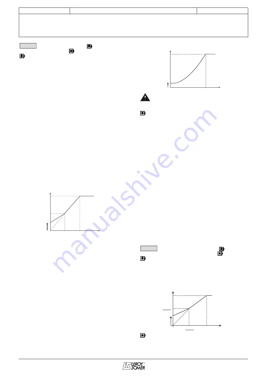
V/F SQUARE (5):
Square law characteristic.
• In mode 4, a volta
g
e is briefly applied to the motor.
For safety reasons, no electrical circuit must be
accessible once the drive has been powered up.
:
Adjustment range : INCREMENTAL (0),
Increm. FD (1), UVW only (2),
Increm. UVW (3),
HALL EFFECT (4),
SENSORLESS 1 to 5 (5 to 9),
RESOLVER (10)
Factory setting
: INCREMENTAL (0)
INCREMENTAL (0): Quadrature incremental encoder.
Increm. FD (1):
Incremental encoder with
Frequency/Direction output.
Function not available in the current version.
UVW only (2):
Channels U, V, W only without their
complement.
Increm. UVW (3):
Incremental encoder with commutation
channels.
HALL EFFECT (4):
Encoder with 6 lines per pair of poles.
SENSORLESS 1 (5) to SENSORLESS 5 (9):
See advanced
parameter
03.38
.
RESOLVER (10)
: Resolver.
The option re
q
uired for mana
g
in
g
the resolver
(
00.14
= 10) is not available.
CAUTION:
The MD-Encoder option is re
q
uired for mana
g
in
g
incremental encoders with or without commutation
channels (
00.14
= 0 to 3) and mana
g
in
g
Hall effect
sensors (
00.14
= 4).
: Low fre
q
uency volta
g
e boost (
)
Encoder lines per revolution (
)
:
Adjustment range : 0 to 25.0% of motor Un (
00.08
)
Factory setting
: 1.0% motor Un
For operation in V/F mode (
00.14
at V/F (2)), parameter
00.15
is used to overflux the motor at low speed so that it
delivers more torque on starting. It is a percentage of the
rated motor voltage (
00.08
).
:
Adjustment range : 0 to 32000 lines per revolution
Factory setting
: 1024 lines per revolution
Used to configure the number of lines per encoder revolution.
Converts the encoder input into a speed.
00.14
Motor voltage
Boost
Motor frequency
00.08
/2
00.08
00.10
/2
00.10
00.15
Motor voltage
Boost
Motor frequency
00.08
00.10
00.15
00.15
Output voltage
Output
frequency
Boost
(
00.15
)
00.08
00.08
2
00.10
2
00.10